Overview
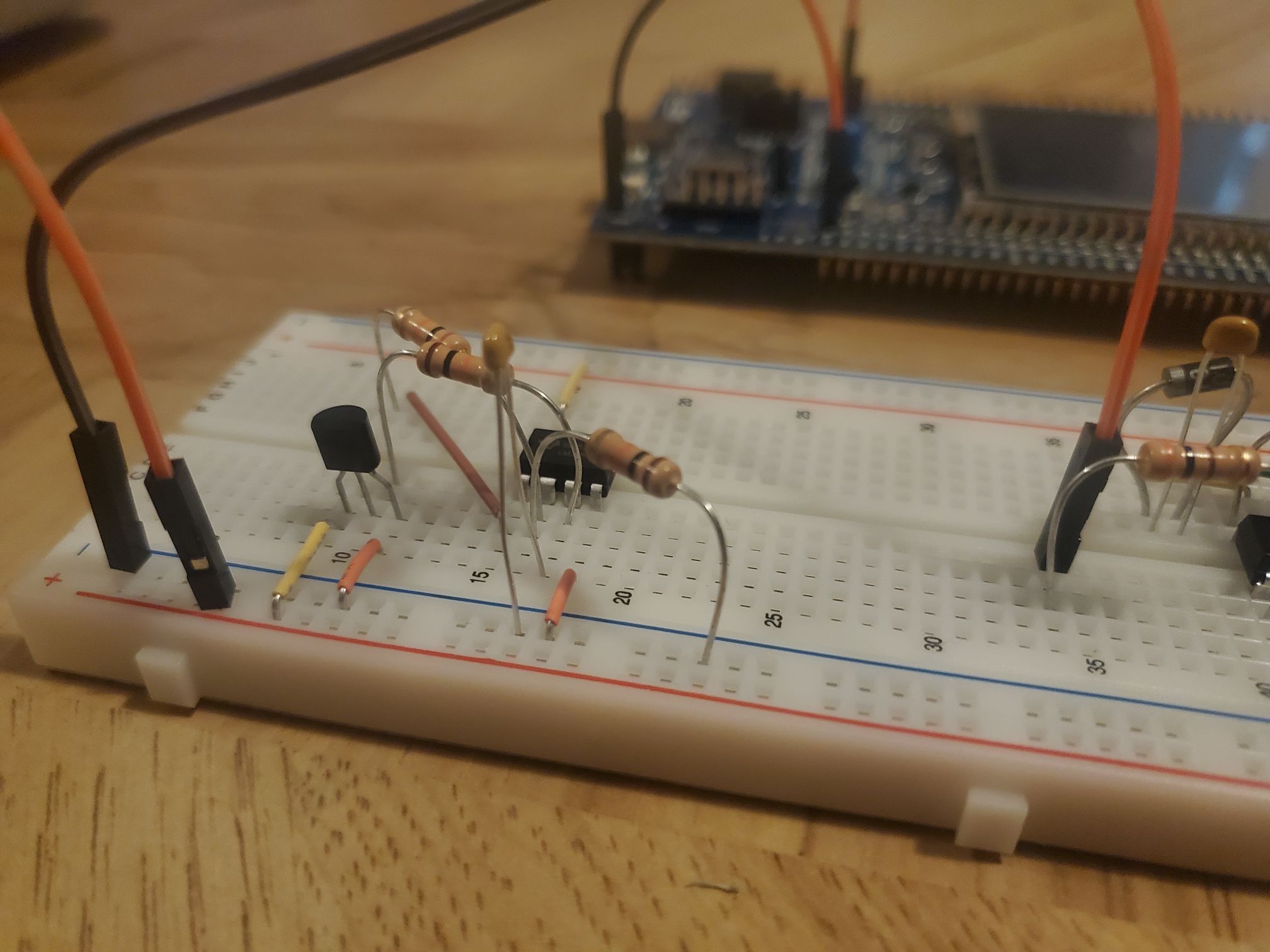
Used and programmed an STM32 MCU system where a fan operating using PWM is triggered based on sensor input.
Problem
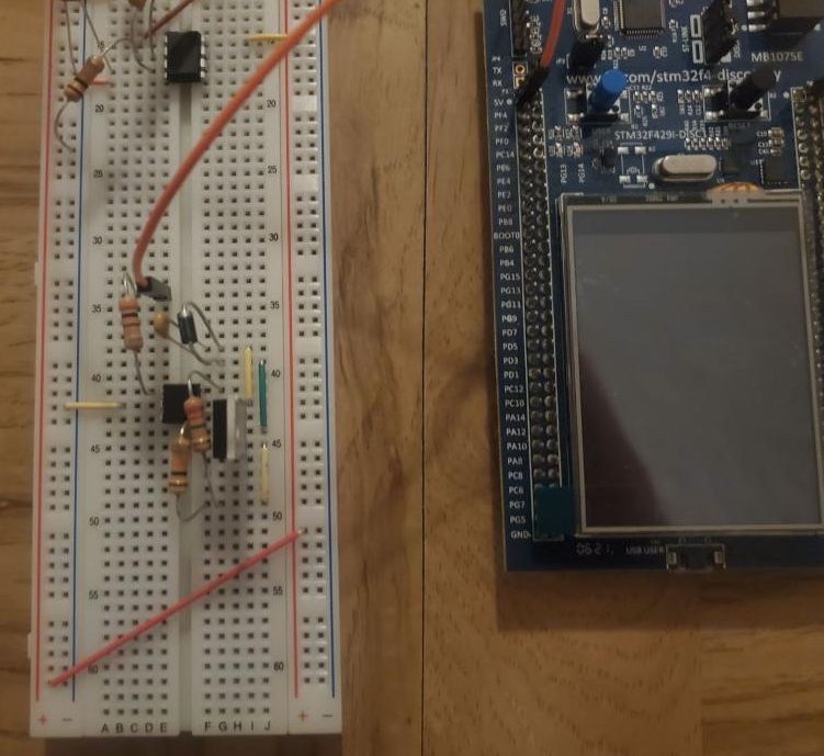
Build a digital thermometer which displays the current temperature and the user selected setpoint on an LCD display. If the temperature exceeds the setpoint, turn on the fan to cool the sensor.
Implementation
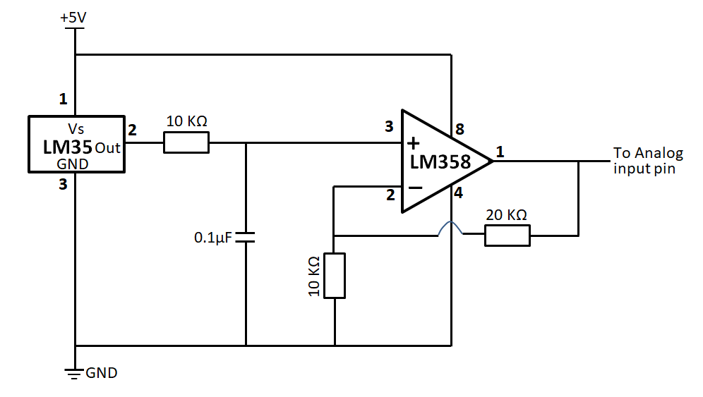
Performed an analog to digital conversion using the MCU to read input voltage. An OpAmp was implemented to bring the feed before the A/D converter to a level where readings would be more accurate. A low pass filter was used to negate spike noise.
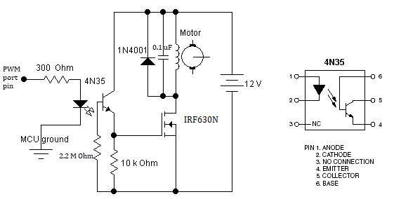
PWM was used to control analog devices with a digital output from the MCU. Even with numerous voltages being applied and removed in an instant, the fan works due to inertia. An advantage is the power saved from only being on for a portion of the total time.
On the display interface, room temperature readings were converted and displayed. Buttons were implemented for manual temperature adjustment.
Results
The final product consists of a fan that is inactive below a certain temperature. Once above the threshold, it spins at a pace relative to the temperature. Full power is reached in hot environments.