Overview
Used and programmed an STM32F429 MCU with a stepper motor. Experimented with how to drive the motor in full/half step mode and clockwise/counterclockwise direction, while controlling the speed of rotation.
Problem
Use stepper motor theory to control the outputs of a motor. Functionality should include step size changes, direction changes, and speed changes.
Implementation
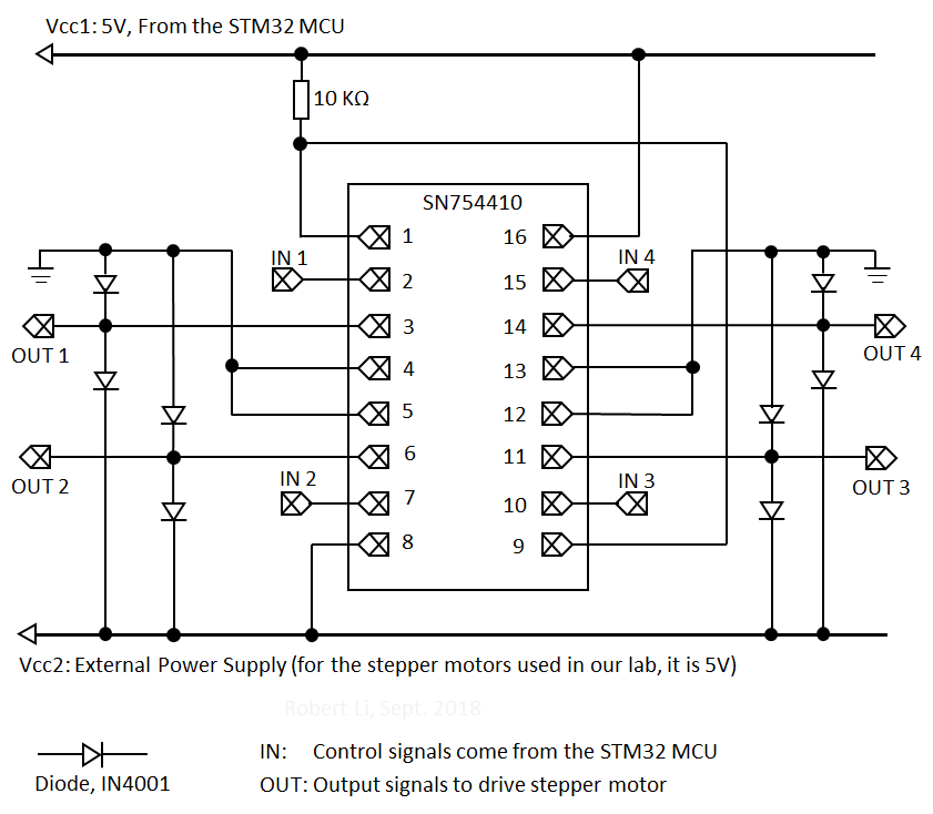
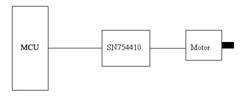
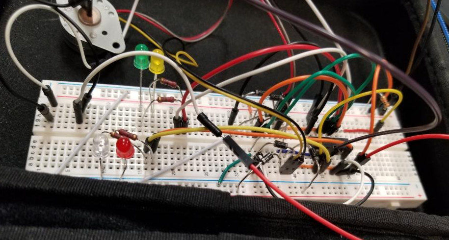
Followed the half bridge diagram with an SN754410NE H-bridge driver for main board wiring.
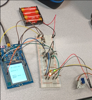
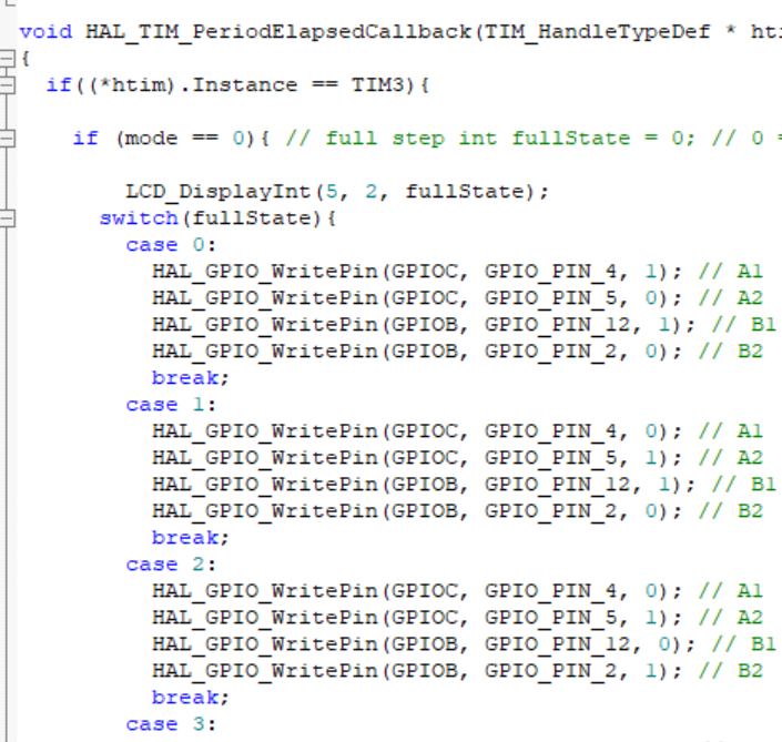
On the STM32, GPIO pin interrupts were triggered via buttons. Using two buttons, the first would define the edit state (0 for full/half step, 1 for cw or ccw, 2 for speed adjustment).
To control step sizes, only certain outputs would be set to HIGH and the remaining to LOW, which induced the rotor coils to align. To change direction, the outputs were reversed. To adjust speed, the timer prescaler values were increased/decreased.
Results
I was able to apply course content to control a stepper motor. Reinforced my understanding of the design process and motor behaviour in response to MCU outputs.