Overview
A digital circuit designed using finite state machines and logic gates to repetitively output my student number on a 7-segment display.
Problem
Use analytical logic and truth tables to develop Sum of Product/Product of Sum expressions for numbers, implement these using logic gates (AND, OR, etc.) and model using Multisim as well as a physical build.
Implementation
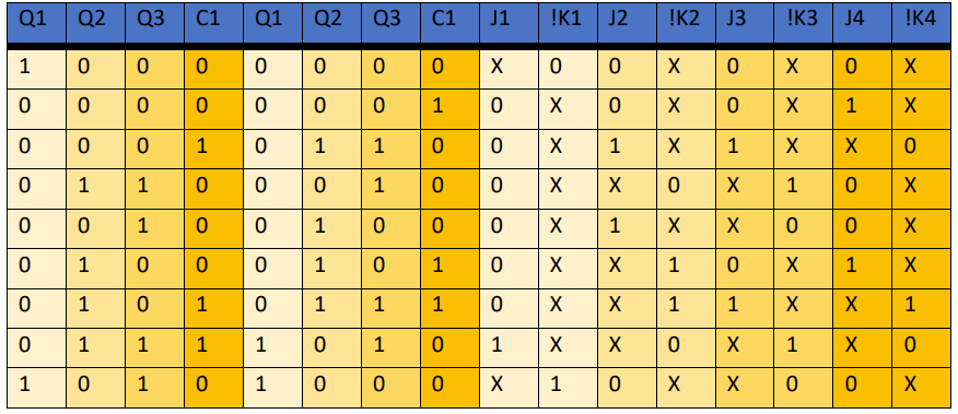
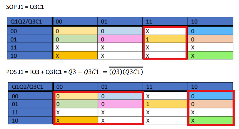
I first started by converting each value to binary, then used an excitation table and truth table. I colour coded everything and made KMaps of each pin output. These expression outputs were optimized based on recurring patterns and choosing between SOP/POS implementation.
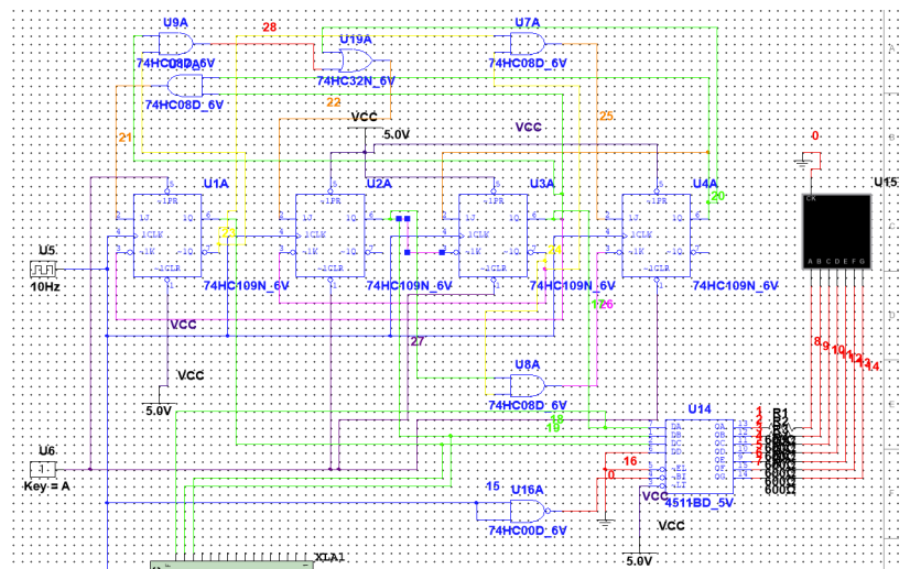
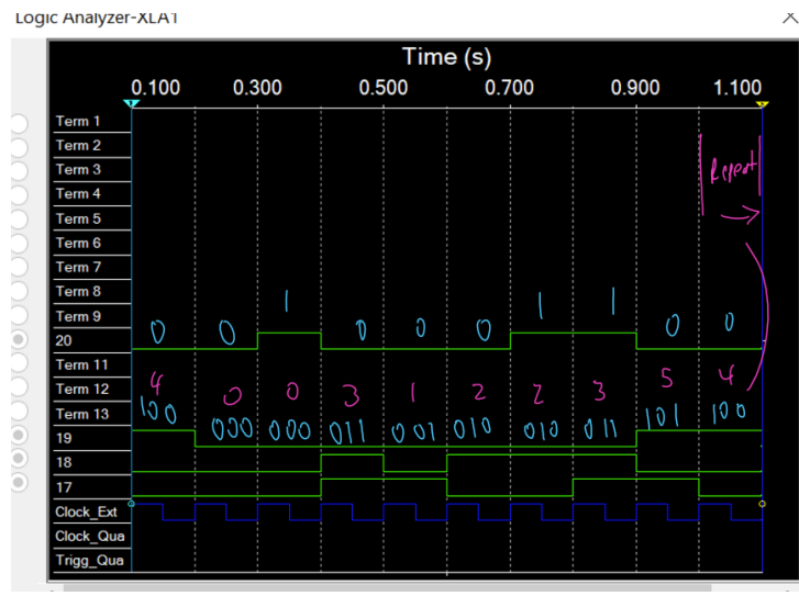
Using Multisim and knowledge of logic gates, I built the circuit using flipflops and decoder chips. I ran timing diagrams to ensure the FSM followed the correct logic and loops properly.
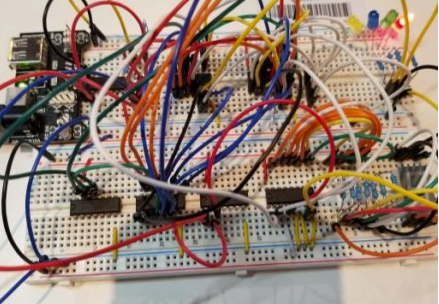
For the final physical build, I laid out the core pieces such as gates and LED, then wired the clock for rising edges to each flipflop. I encountered problems where the 7-segment display wasn’t working and outputs weren’t as expected. I repetitively followed wires in accordance to my simulation but ultimately had to redo the wires.
Results
I was able to create an infinitely looping digital circuit using the principles of my Analog and Digital Circuits course. I furthered my understanding of gate theory and physically applied these concepts.