Overview
I designed and engineered a 1:20 scale model of a Nissan Rogue SUV as part of a mechanical design course. The project followed a complete engineering design cycle: defining requirements, modeling systems in CAD, simulating behavior, optimizing structures, and generating manufacturable drawings. All motion was mechanically driven using a mid-mounted motor and gear train, without steering or electronic control modules.
Problem
Design a mechanically driven RC car using constraints based on my student ID, including a mid-mounted motor, a 16:28 gear ratio, and SUV body type. The car had to be structurally sound under load, use realistic tolerances, and demonstrate manufacturability.
Implementation
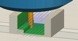
Gear Train and Motor Assembly
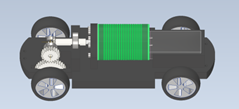
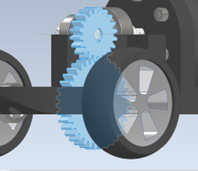
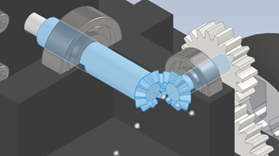
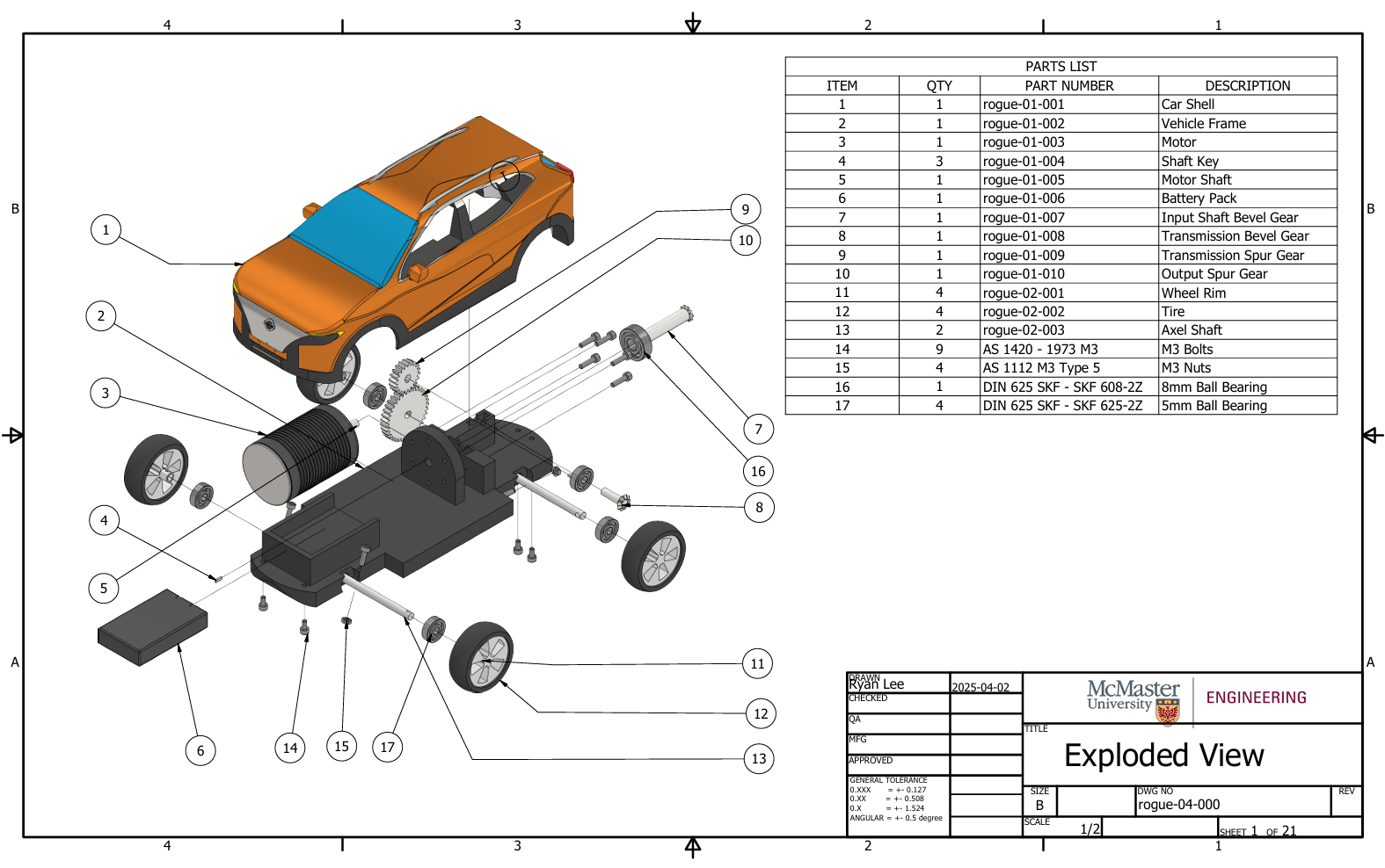
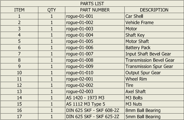
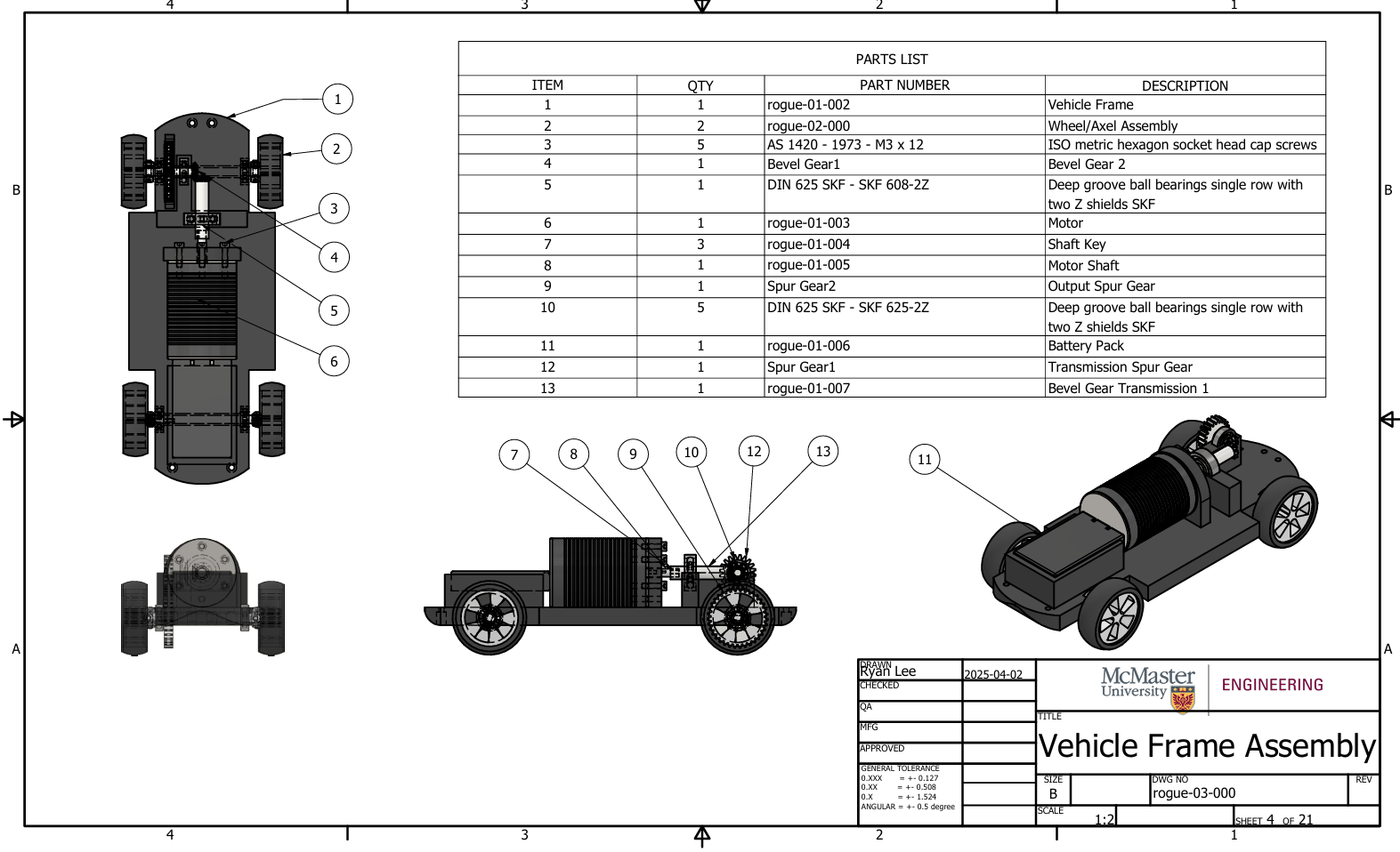
The drivetrain used bevel gears to redirect torque from the motor shaft by 90 degrees to the rear axle. I used Autodesk Inventor’s gear generator to achieve the required 4:7 gear ratio using 20- and 35-tooth spur gears. I designed a custom shaft key and press-fit connections to link rotating parts, ensuring reliable torque transmission through the system.
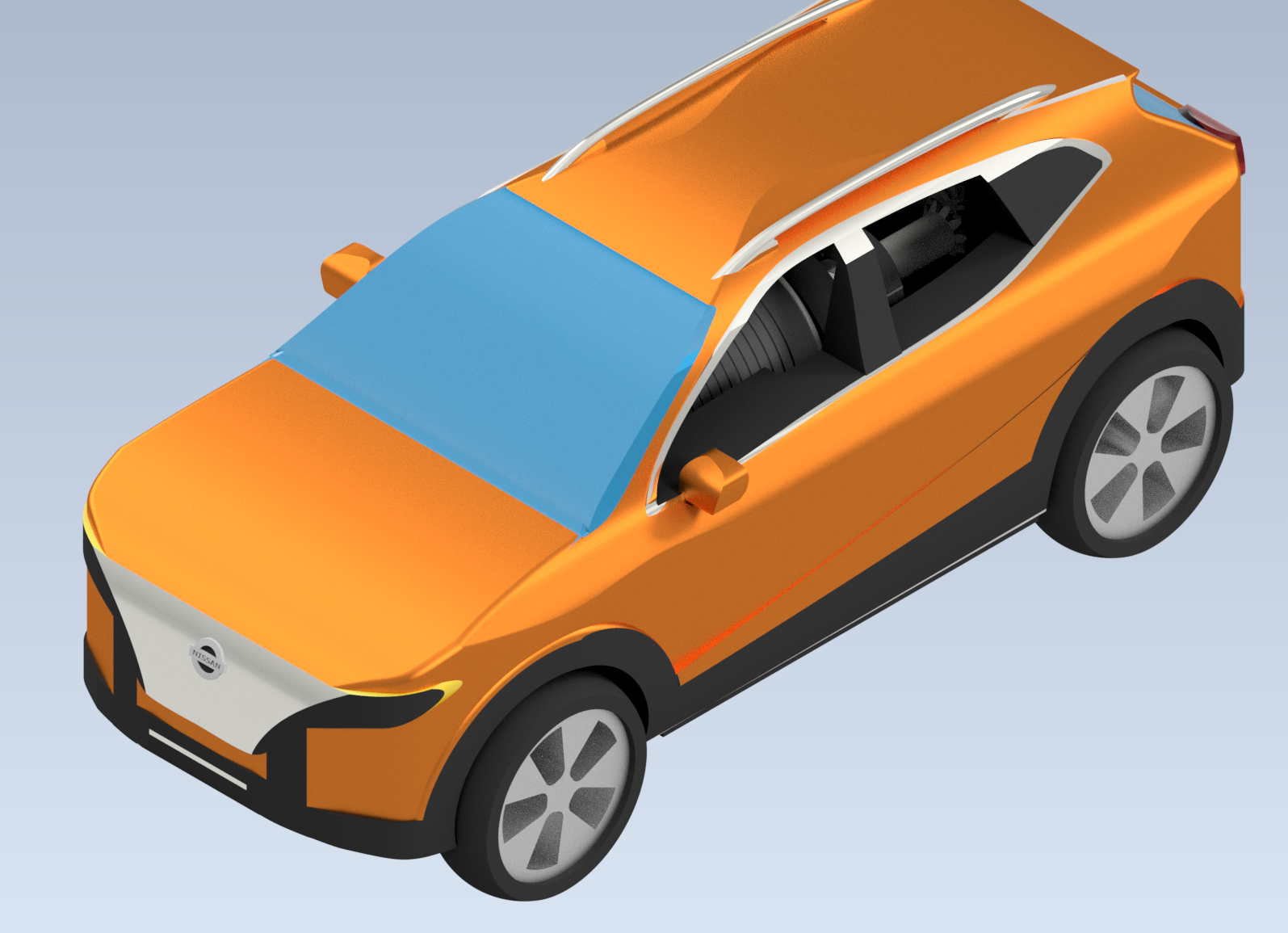
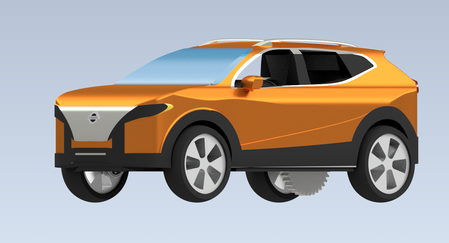
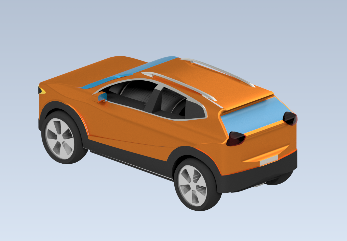
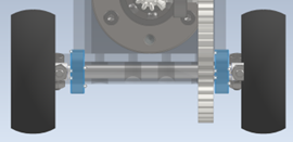
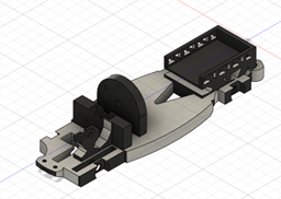
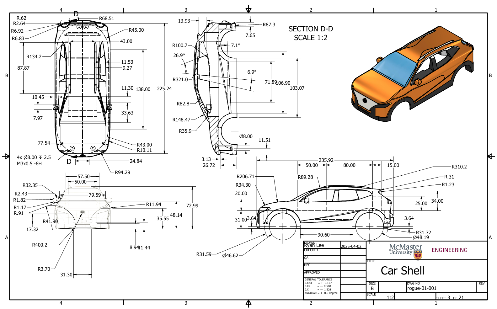
Vehicle Frame and Body
I modeled the vehicle shell based on orthographic views of a Nissan Rogue and scaled it to match a 1:20 ratio. The frame houses the drivetrain, battery pack, and wheel supports, and was modeled with tolerances to account for 3D printing and CNC manufacturing constraints.
Engineering Analysis
Motion Simulation
A full kinematic simulation of the drivetrain validated that the motor correctly rotated all gears and rear wheels through the specified gear ratio. The motor rotated 1000 degrees during the simulation, confirming uninterrupted torque transmission through all shafts and gear stages.
Structural Stress Analysis
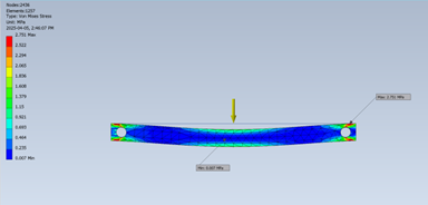
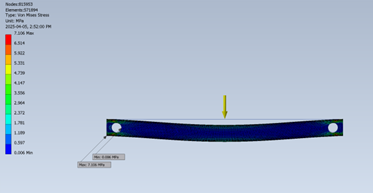
To ensure the axles could withstand static and dynamic loads, I ran stress simulations assuming a total car weight of 1.2 kg. The shaft deflection converged to 0.0045 mm, and Von Mises stresses stayed below 7.1 MPa—well under the 95 MPa yield strength of aluminum 6061.
Shape Optimization
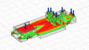
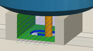
I applied a static shape optimization to the vehicle frame to reduce weight and material usage while preserving structural integrity. Using Fusion 360’s simulation workspace, I generated a stress map and removed low-stress regions, demonstrating a practical application of topological optimization.
Results
The completed model met all design requirements and performed as intended. I demonstrated a solid understanding of drivetrain mechanics, structural analysis, simulation techniques, and optimization. This project taught me how to balance precision with manufacturability and weight with strength.