Overview
A steel ball balancing platform with 2 degrees of freedom using a PID controller algorithm.
Problem
In one of our Control Systems classes, 3DA4, we used Simulink, 1 DoF ball balancing beam, and a PID controller to balance a steel ball. I decided to expand upon this and create a platform balancer with an X and Y axis controller!
Planning
My initial plan to control the platform axes was to use MG90s Servos, but after rough prototyping, I found that the torque provided at a given speed would not be suitable. As a result, I looked into stepper motors and settled upon the Nema 17 Stepper Motor.
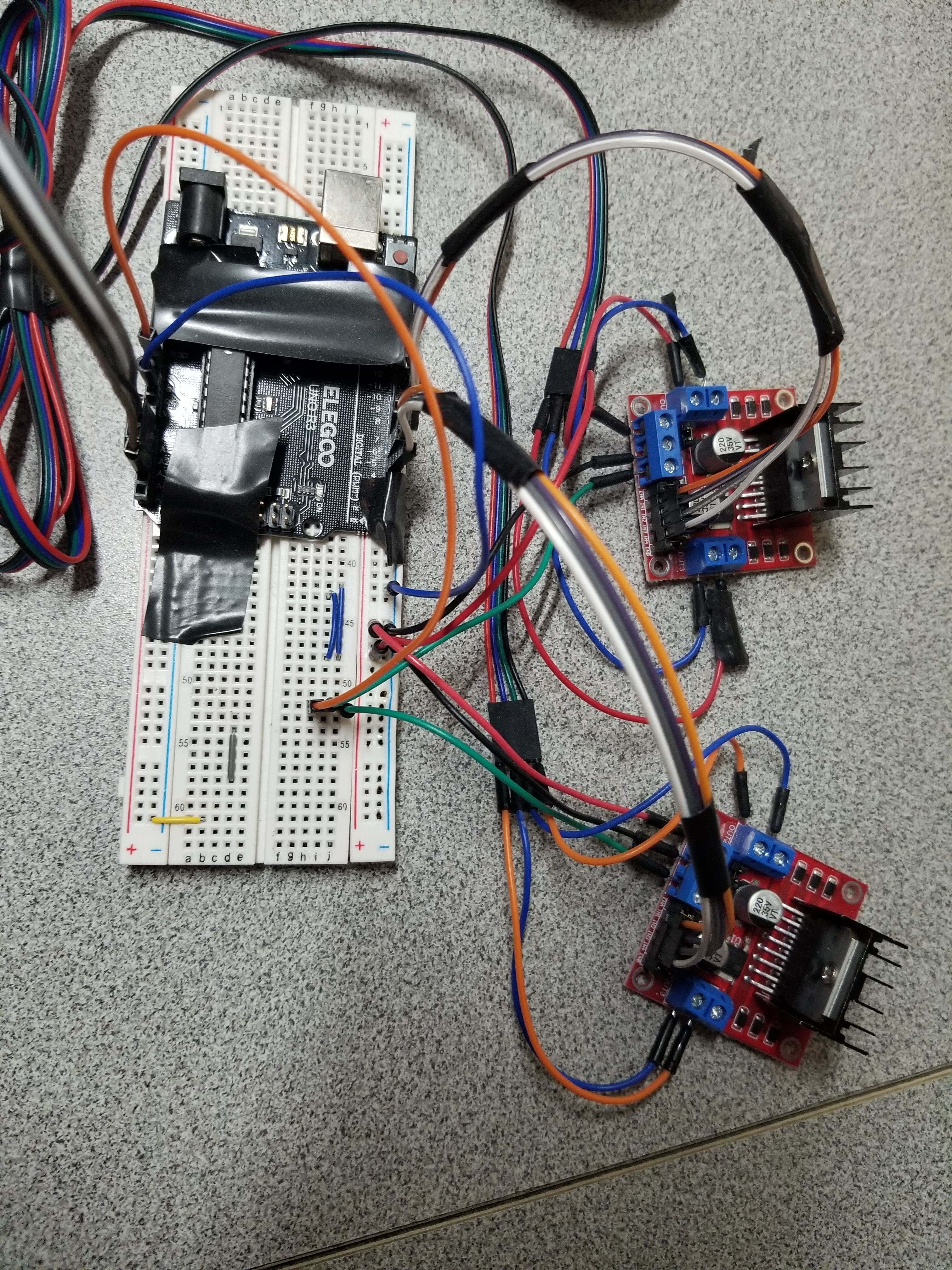
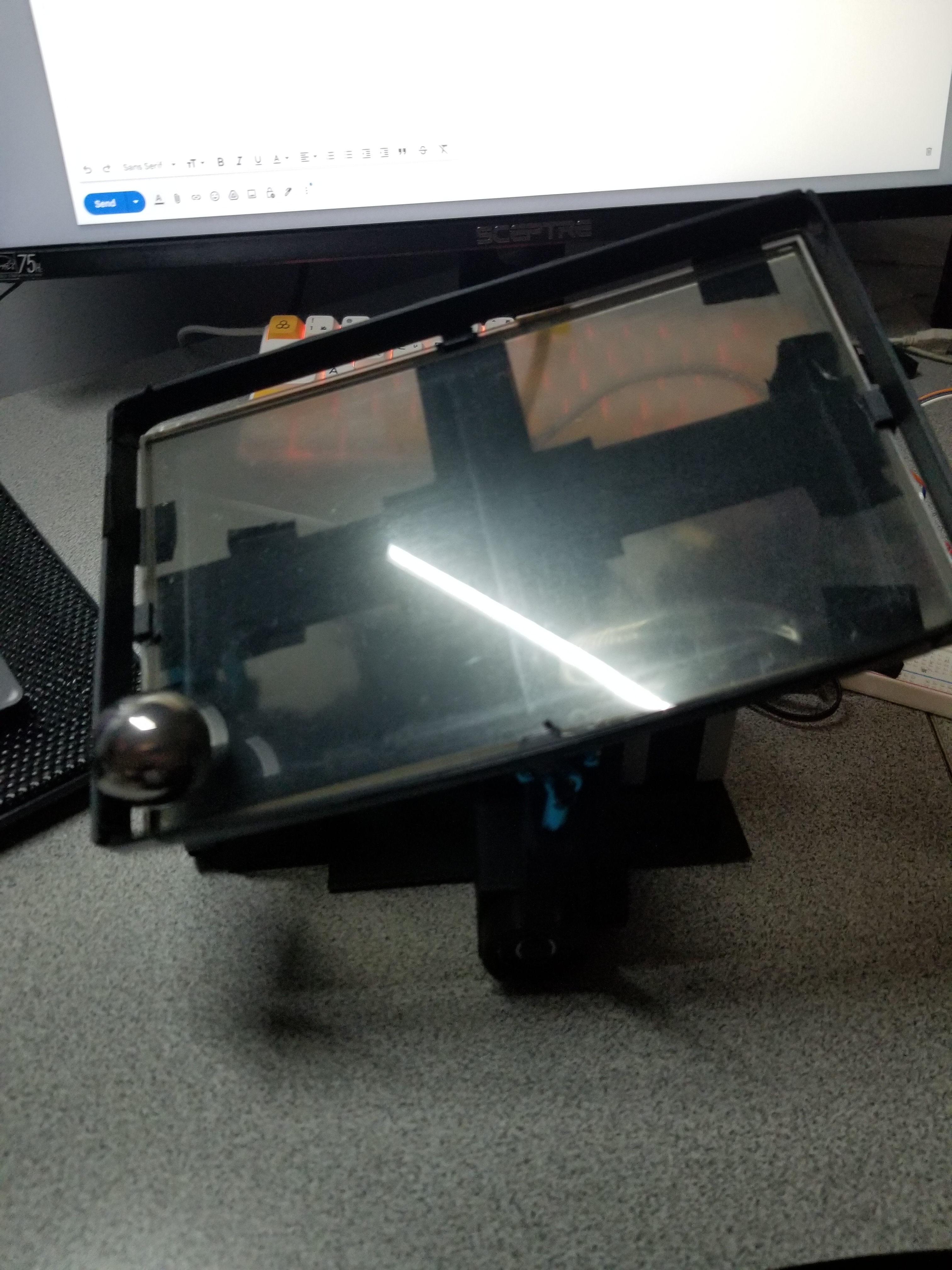
To control the steppers, I decided on using L298N Motor Controller. To determine the position of the steel ball, I settled on using a resistive touch pad as opposed to ultrasonic sensors or a camera.
Implementation
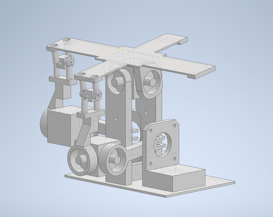
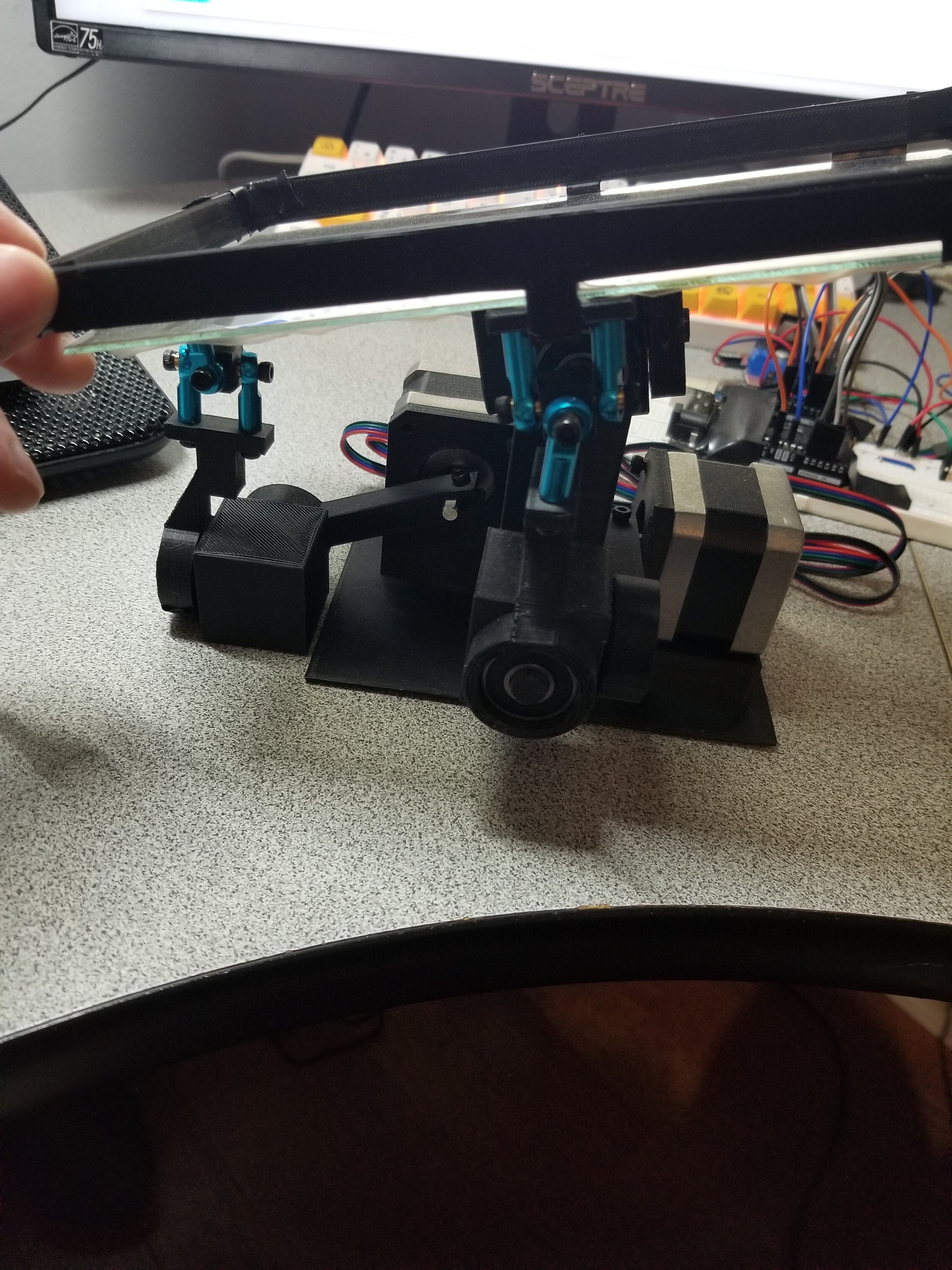
In order to move the platform in 2 degrees of freedom from a single degree of freedom input (stepper shaft rotation), I needed 2 ball joints. This was accomplished by using 2 ball bearings, as well as 4 ball joint tie rods that I made a mini “makeshift” ball joint with.
Troubleshooting
The first problem I encountered was shake and wobbliness in the entire build. I resolved this through tighter tolerances and adding supports to the middle joint.
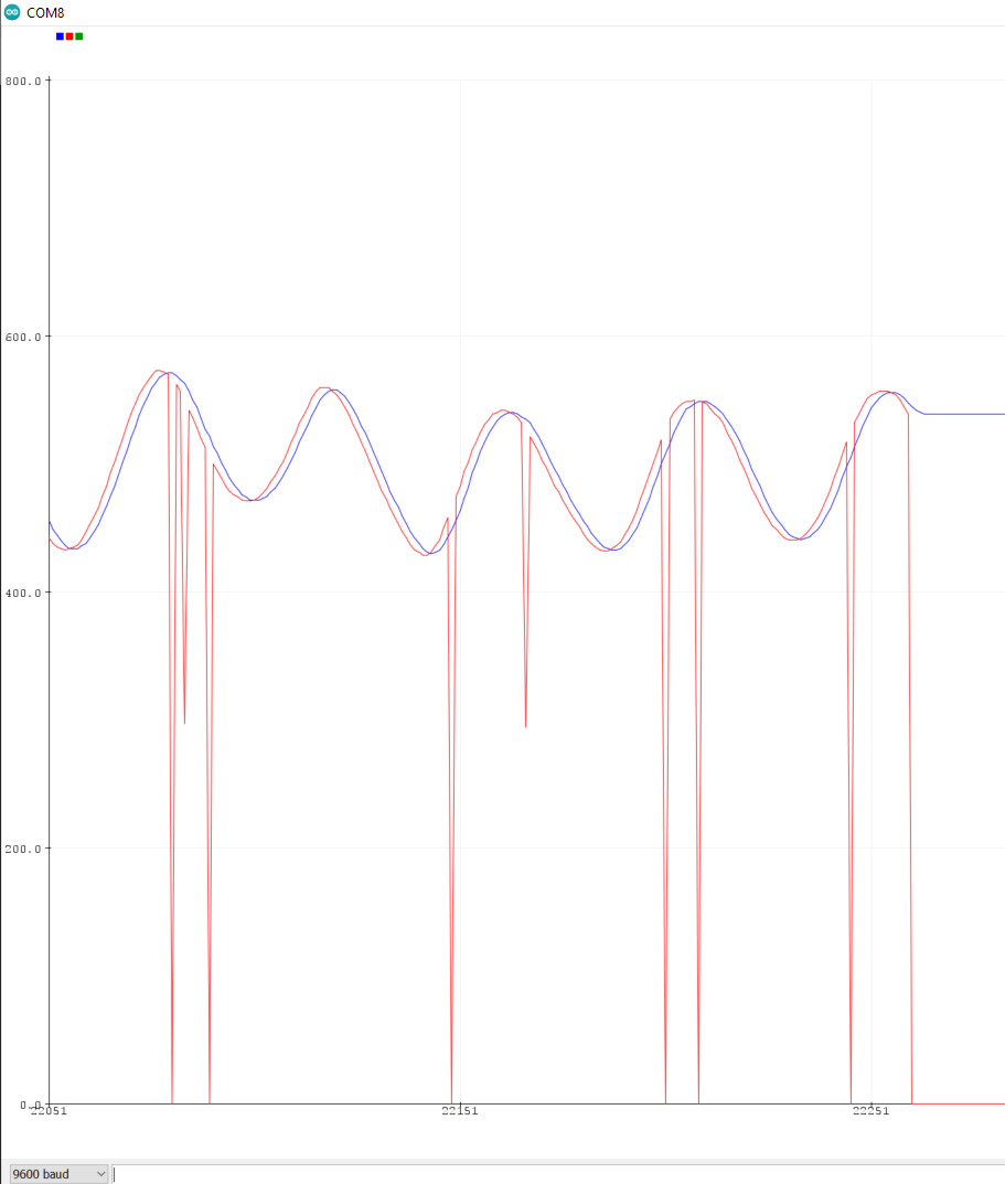
The largest issues had to do with the software implementation. Unfortunately, the resistive touch pad produced extremely noisy signals. I attempted to resolve this using a moving average filter.
The most tedious part was tuning—a trial and error process for finding Proportional, Integral, and Derivative constants based on the system response. I built brackets to keep the steel ball contained, as well as barriers when tuning each axis.
Results
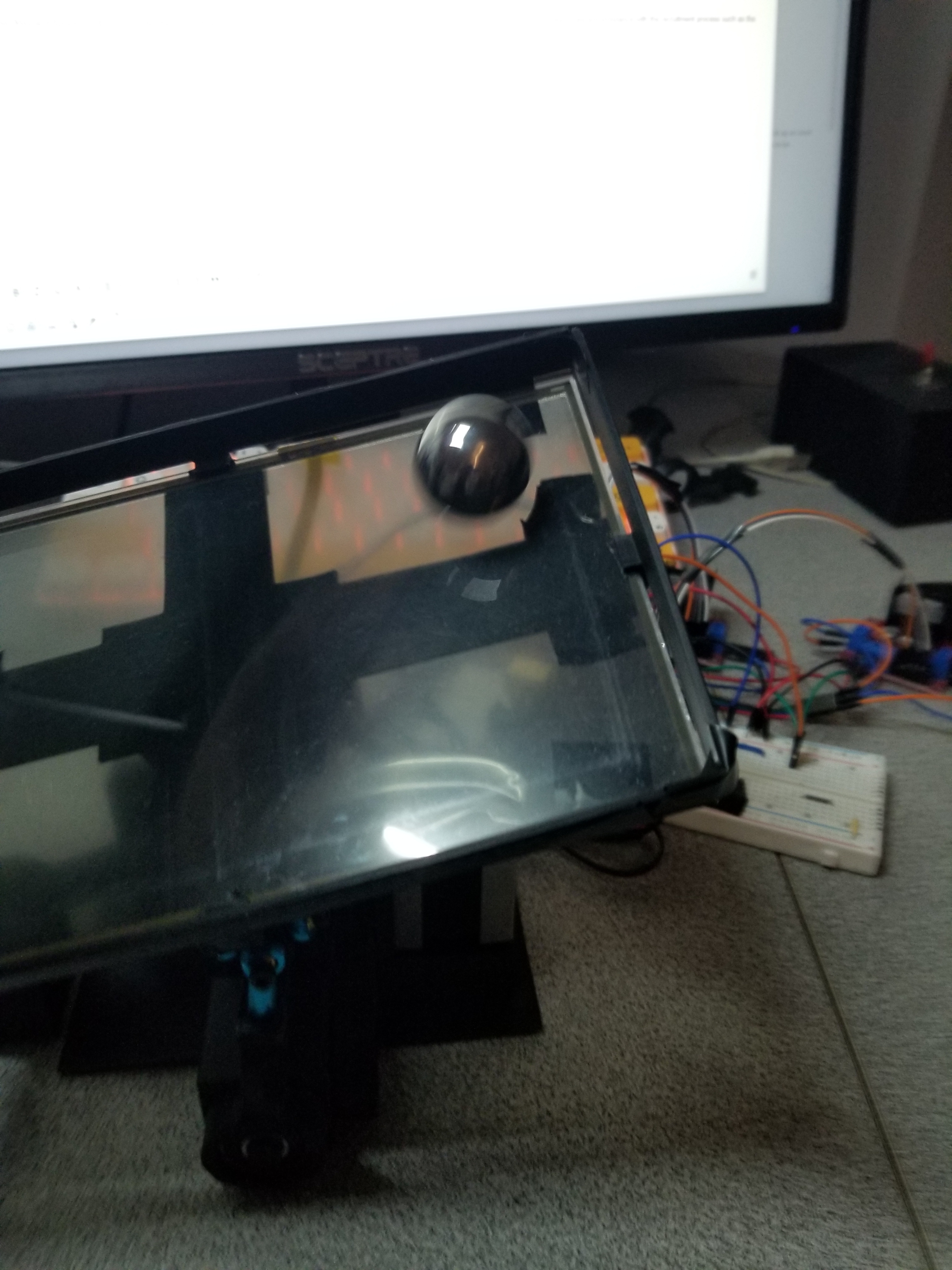
I was able to make a somewhat-tuned platform ball balancer using PID algorithms. The biggest takeaway was my research into PID algorithms and applying them. This project required a balance in everything—stability, print times, ease of assembly, and much more.