Overview
Baja SAE is an off-road racing competition where university teams design and build single-seat vehicles to tackle extreme terrain. Data acquisition helps collect real-time vehicle data, allowing for performance optimization and better tuning of vehicle components.
What is Data Acquisition?
Data acquisition (DAQ) involves using sensors and embedded systems to collect critical performance data from various parts of the Baja car. This includes RPM, throttle position, strain, suspension travel, and brake pressure. The gathered data is analyzed to enhance the vehicle’s reliability and efficiency.
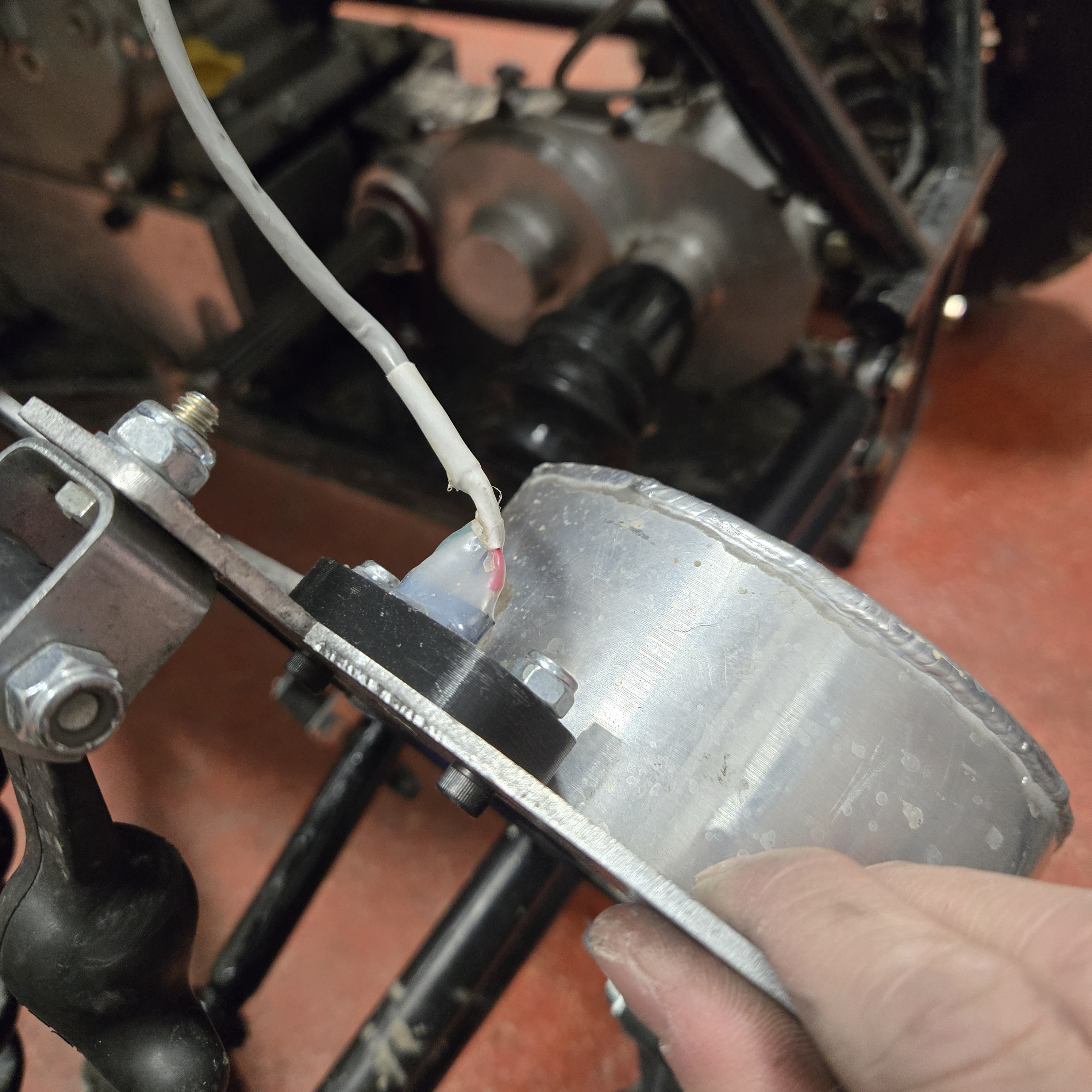
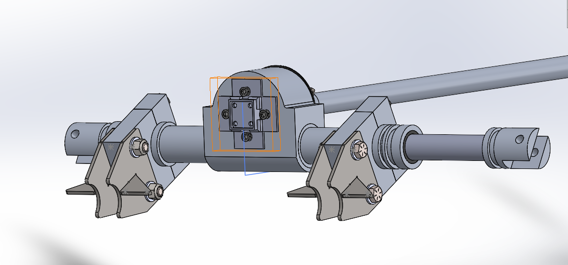
Primary/Secondary CVT Sheave RPM
What it is:
Tracks the rotational speed of the primary and secondary sheaves in the continuously variable transmission (CVT). This data helps assess shifting performance and overall CVT efficiency, assisting in tuning the drivetrain for optimal acceleration and power delivery.
How it works:
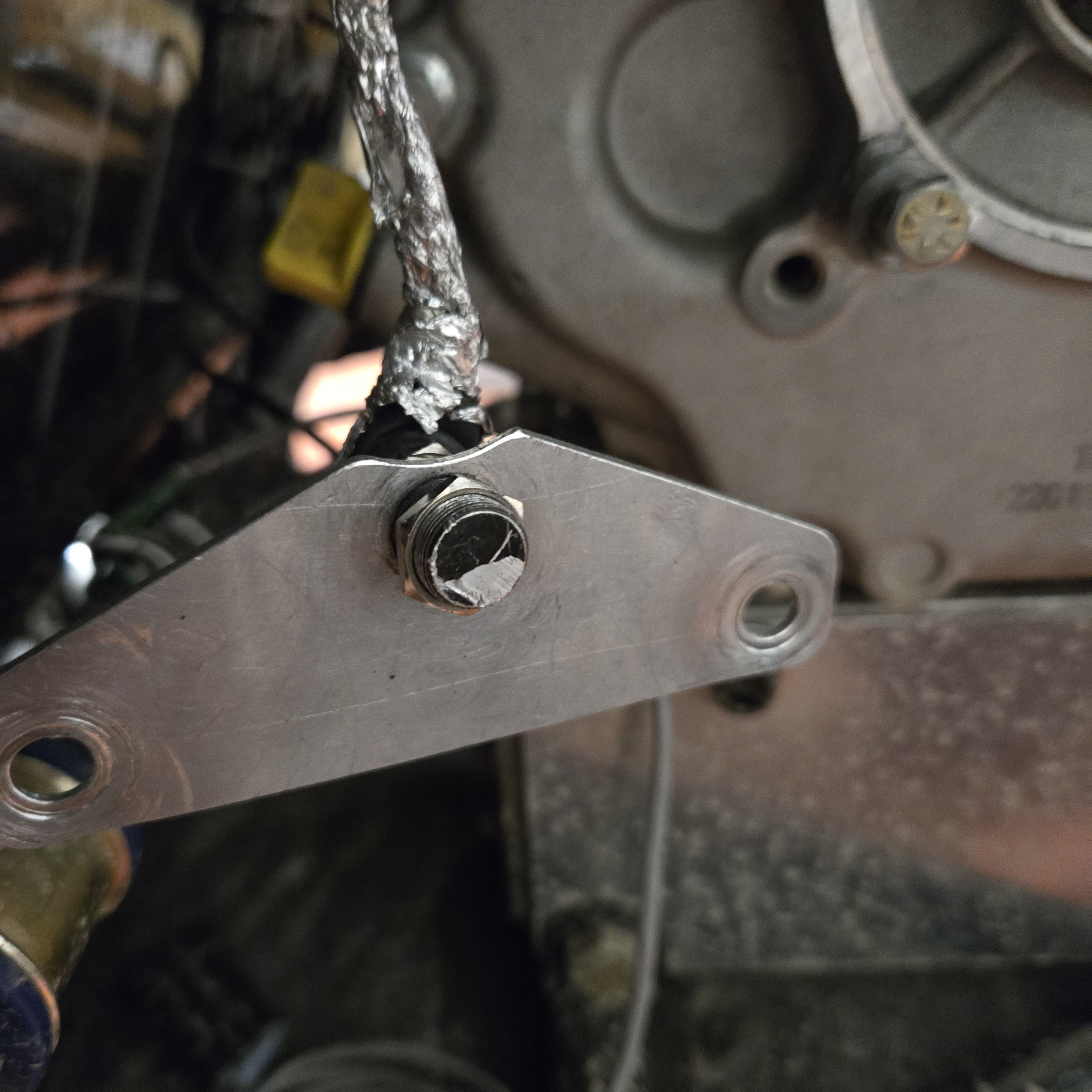
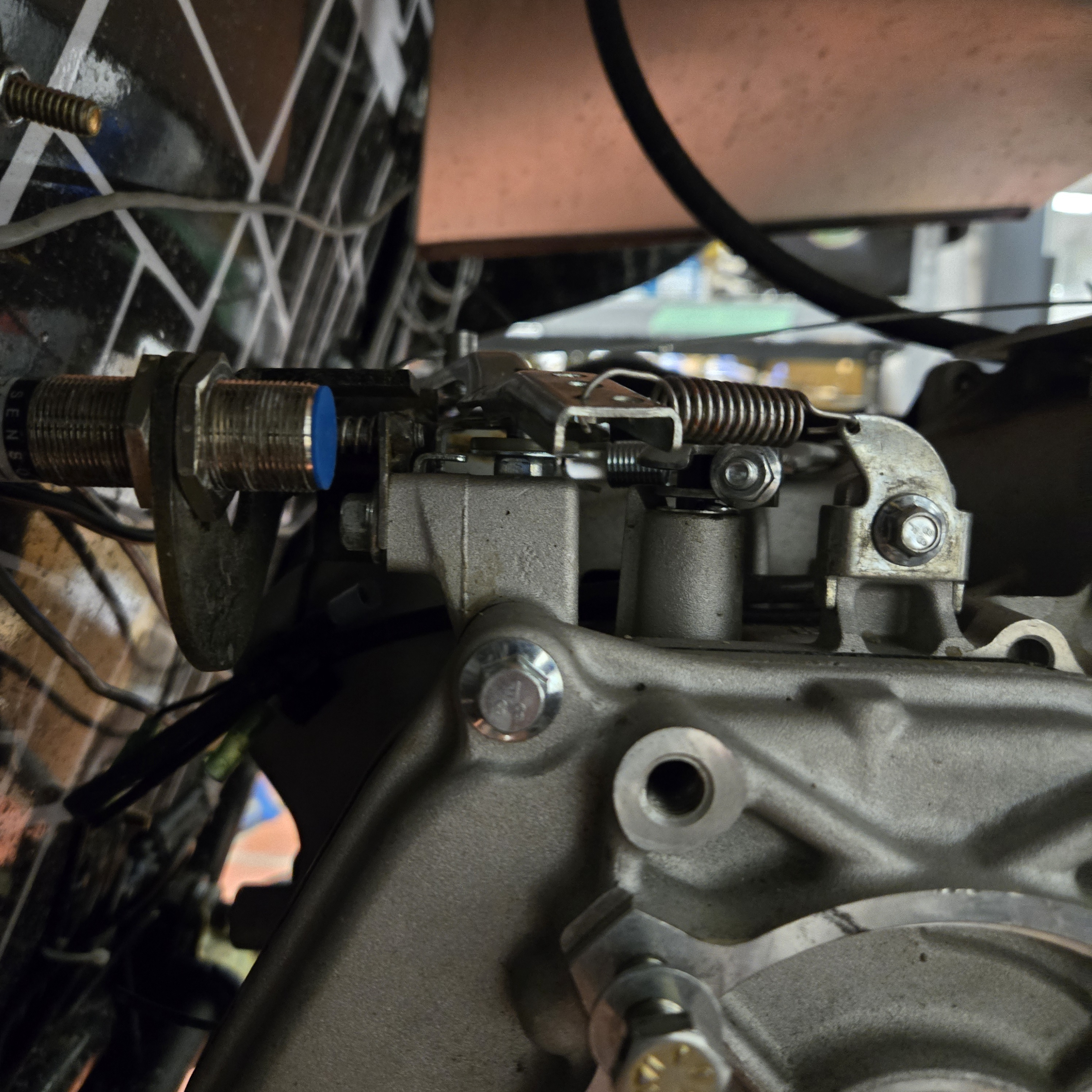
Originally, a hall-effect sensor and magnets were used, detecting pulses each time a magnet’s positive edge passed the sensor. While effective, this method had reliability concerns due to magnet placement failures. We transitioned to an inductive sensor mounted beside the brake rotor with strategically shaped cutouts, eliminating the need for mounted magnets and increasing durability. This data is crucial for CVT tuning, helping us determine engagement points and optimize shift curves.
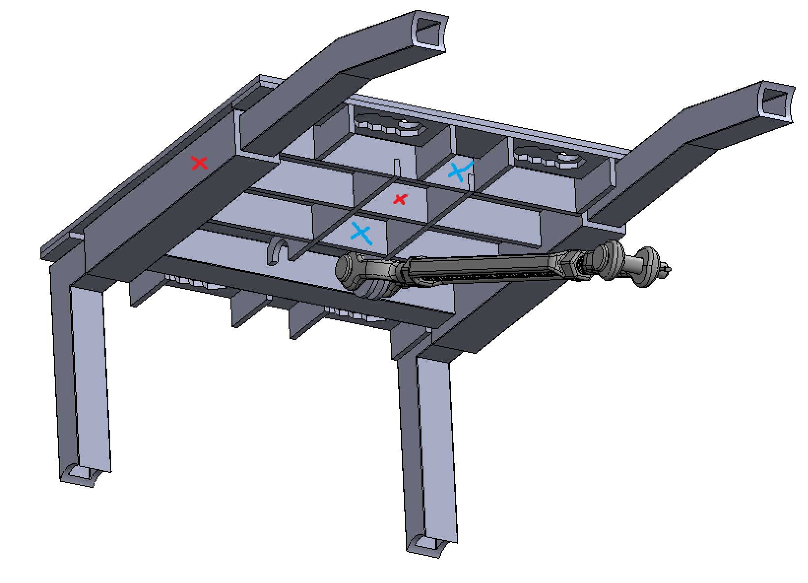
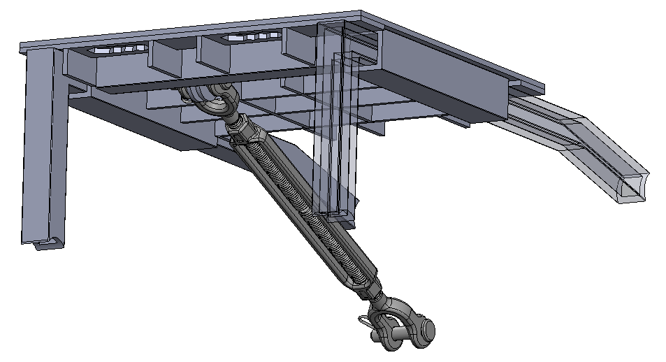
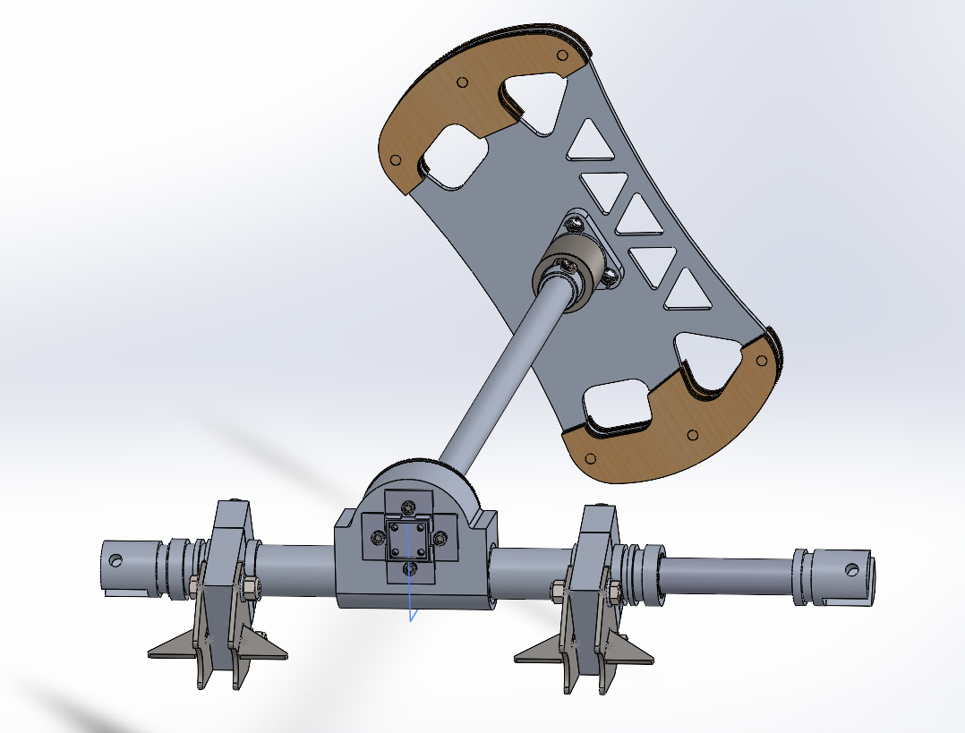
Suspension Travel
What it is:
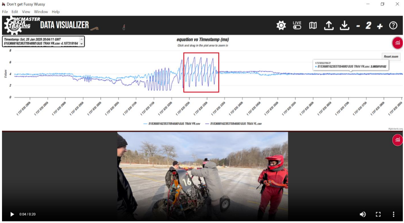
Measures the movement of the suspension system to analyze damping characteristics and spring behavior, providing insights into ride quality and handling performance.
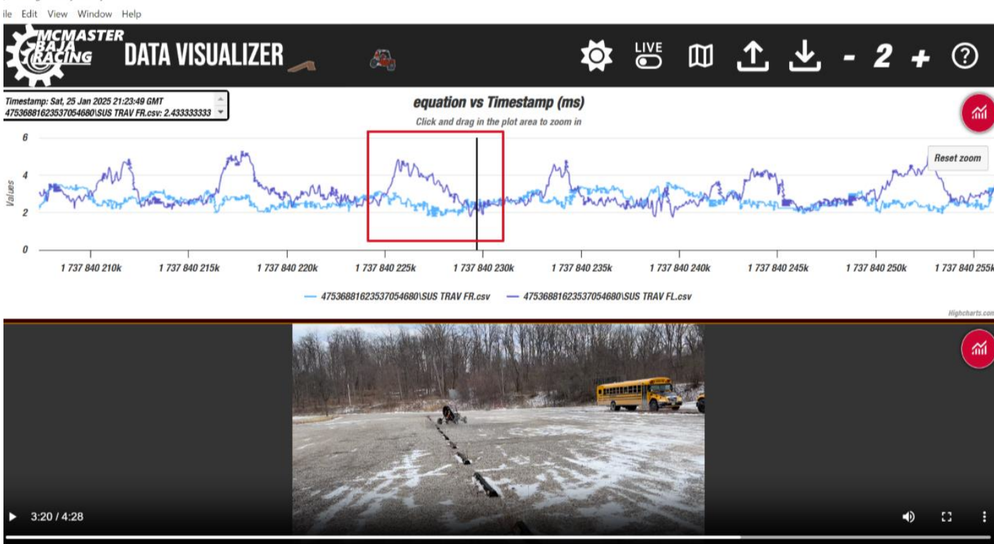
How it works:
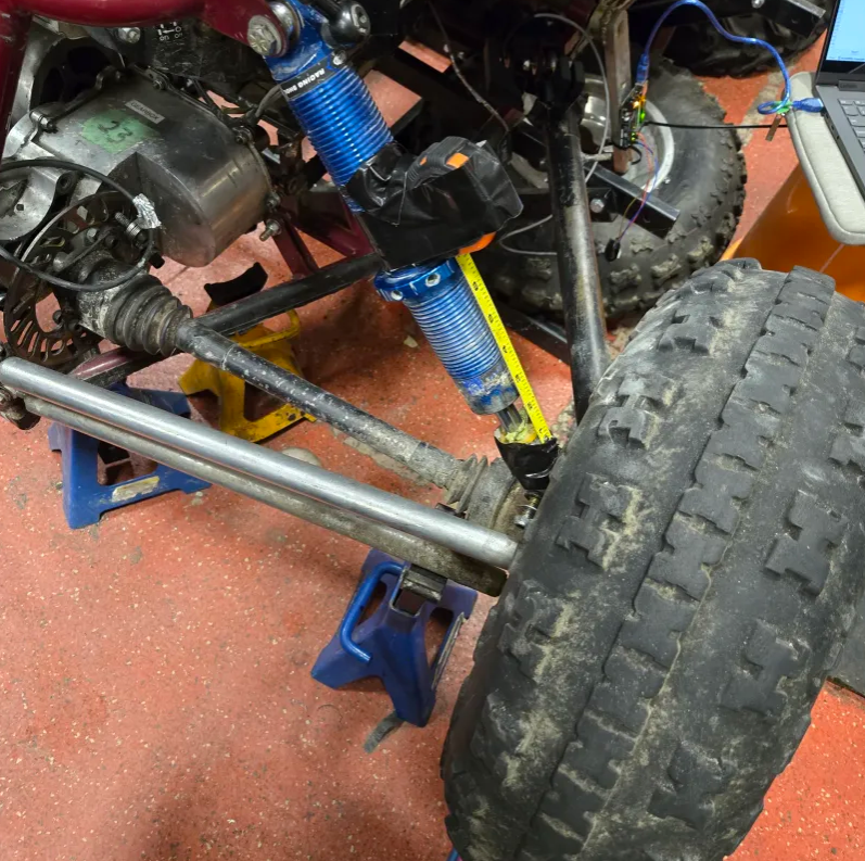
Utilizes bipolar hall-effect sensors to track the position of magnets mounted on the trailing link. This allows us to correlate suspension compression with forces experienced on the chassis. The data is used to tune spring rates and damping, ensuring the suspension system absorbs impacts effectively. Additionally, it works alongside strain gauges on the anti-roll bar to optimize weight distribution and reduce unnecessary chassis movement.
Sheave Position
What it is:
Measures the exact position of the primary and secondary CVT sheaves to analyze gear ratio changes and optimize shifting performance. Helps validate whether CVT behavior matches theoretical shift curves.
How it works:
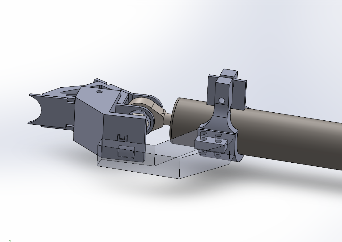
We are integrating time-of-flight (ToF) sensors with ±0.1” accuracy to detect precise sheave movement. This data, combined with wheel RPM, provides insights into CVT efficiency and engagement points. Challenges include mounting inside the CVT case, ensuring robustness against vibration and heat, and compliance with competition rules.
Engine Runner Vibration & Seat Vibration
What it is:
Measures engine mount vibrations and seat vibrations to optimize structural integrity and driver ergonomics. Reducing excess vibrations improves power transfer and enhances driver comfort in long endurance races.
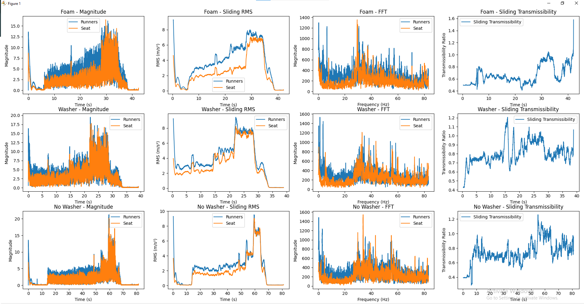
How it works:
Accelerometers mounted on the engine runner measure vibration levels and detect resonance frequencies. Fast Fourier Transform (FFT) is used to analyze frequency components, helping us optimize mount design and weight savings while maintaining strength. A similar approach is used for seat vibration analysis, where accelerometers assess driver fatigue due to prolonged exposure to vertical and horizontal oscillations.
Engine Dynamometer (Dyno)
What it is:
A stationary test stand for tuning the engine and CVT without needing full vehicle testing. Allows us to analyze power output, torque, and shifting behavior in a controlled environment.
How it works:
The engine is mounted onto a test stand equipped with a CVT, braking system, and throttle control. Sensors track engine RPM, output torque (via strain gauges), and shifting behavior to fine-tune the CVT without requiring an entire drive day.
Steering Column Angle
What it is:
A Hall Effect sensor (AS5600) mounted on the steering column tracks the driver’s steering angle using a diametrically magnetized magnet. This data helps analyze steering performance, alignment drift, and driver effort.
How it works:
The AS5600 sensor detects the angular position of the magnet as the steering wheel turns, providing precise real-time feedback on steering input. This data is used alongside strain gauges on the steering column to evaluate steering resistance and optimize driver ergonomics.
Throttle Position
What it is:
Measures the throttle lever position using a Hall Effect sensor to track driver input and correlate it with engine RPM and CVT behavior.
How it works:
A Hall Effect sensor mounted on the throttle lever detects angular displacement of a diametrically magnetized magnet. This gives a proportional voltage output corresponding to the throttle position, which is logged alongside RPM and CVT data to analyze driver behavior and optimize engine response.
Brake Fluid Pressure
What it is:
Monitors brake fluid pressure to assess braking force and validate brake system performance under various conditions.

How it works:
A pressure transducer is connected to the brake line to measure hydraulic pressure in real time. This data is used alongside deceleration data from the accelerometer to analyze brake effectiveness and optimize the brake system for competition.