Overview
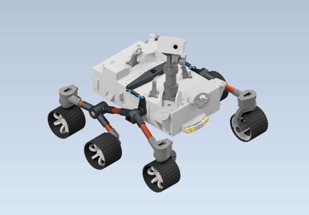
Inspired by my passion for space exploration, I set out to create a scaled-down functional replica of the Perseverance Mars rover. The goal was to replicate its key systems, including the rocker-bogie suspension, motorized wheels, and live camera module, while adapting the design to materials and components accessible for a hobbyist build.
Problem
I wanted to develop a well-engineered, flushed-out robotic vehicle that mimicked the real Perseverance rover, with functional movement and control systems. The challenge was to scale down the design effectively while maintaining structural integrity and maneuverability.
Implementation
Step 1: Initial Research & Design
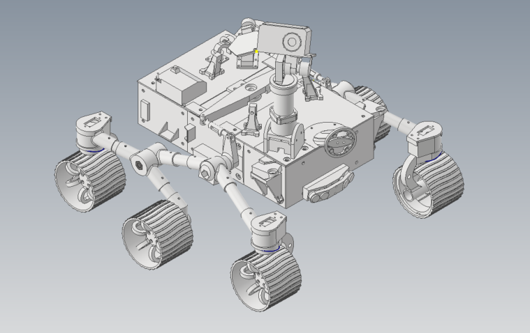
I started by analyzing a high-detail Blender model of the Perseverance rover found online. By capturing images of each face and measuring key dimensions, I determined an appropriate scale of 30:1. I designed the rocker-bogie suspension in CAD using copper pipes, tie rods, and bearings.
Material selection was a key aspect: structural parts were 3D printed using PLA+ for increased strength, aluminum profiles for the chassis, and TPU for the wheels to improve traction.
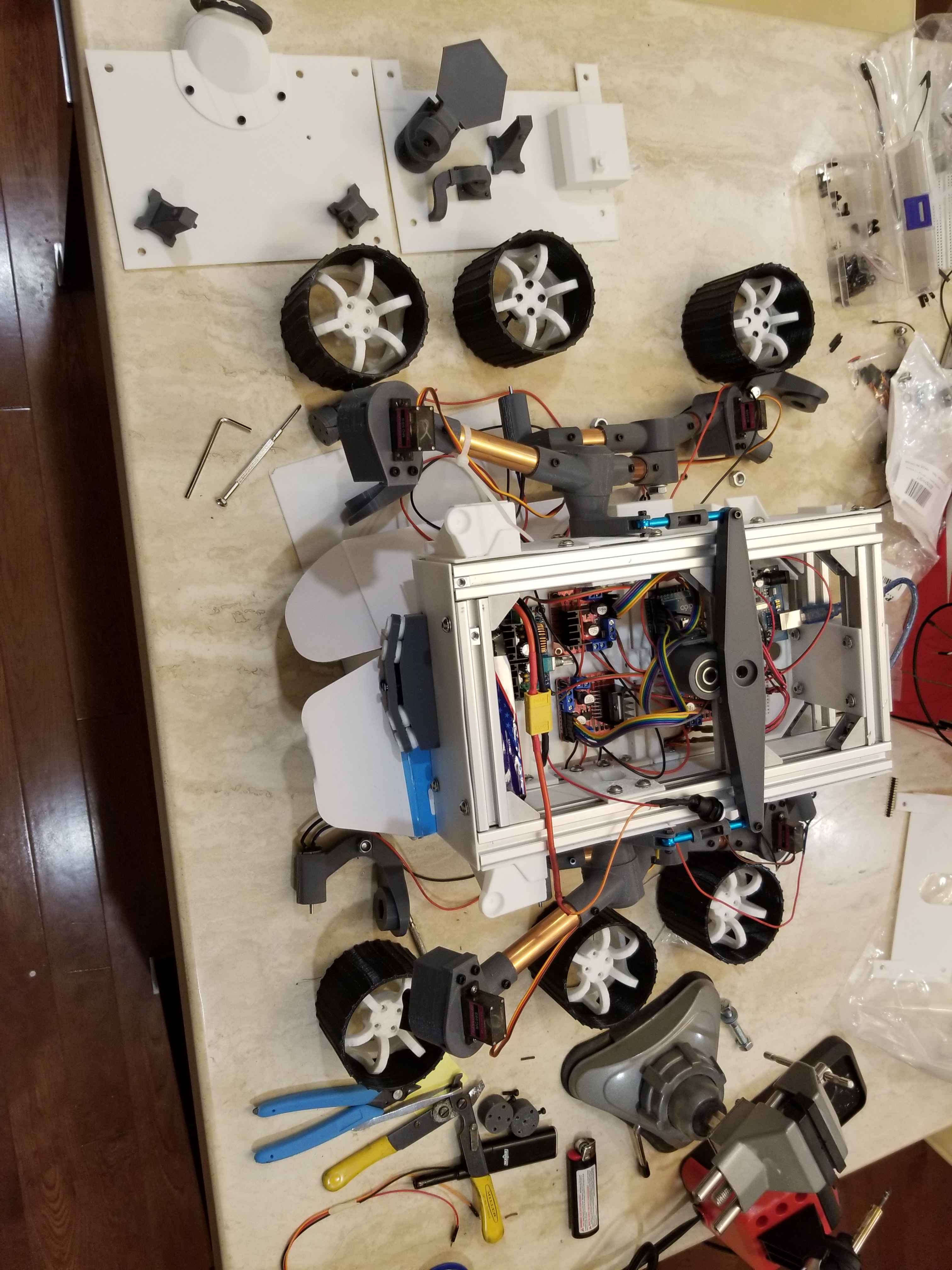
Step 2: Manufacturing & Assembly
The aluminum chassis required precise cutting and drilling using a drill press. 3D printing was a significant part of the process—I experimented with infill density, print orientation, and layer height. During assembly, I carefully aligned the rocker-bogie mechanism with bearings at pivot points to reduce friction.
Step 3: Electronics & Control System
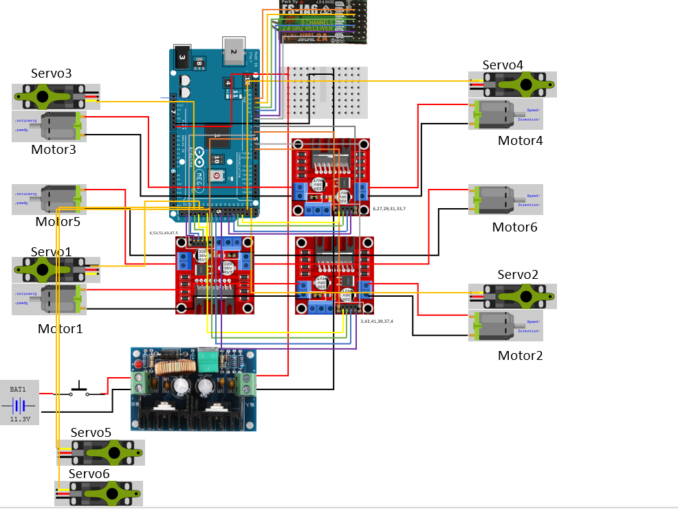
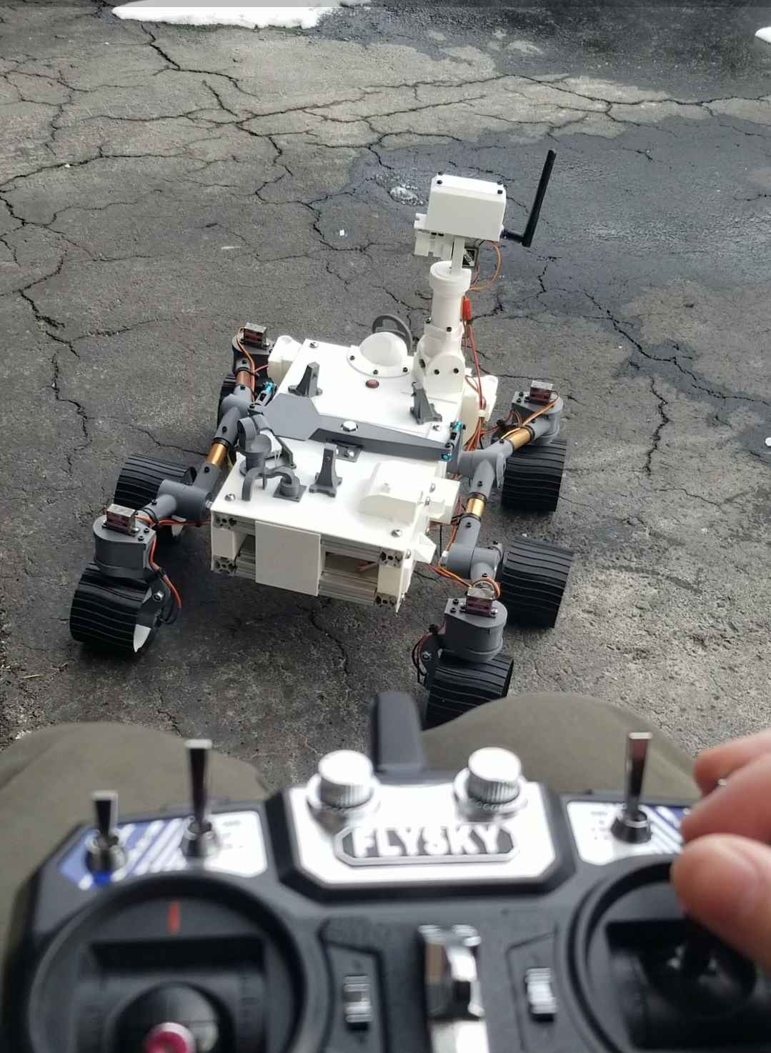
A 12V LiPo battery served as the main power source, with a buck converter stepping down voltage for DC motors. Each wheel was powered individually via motor drivers. Steering was handled using servo motors. The rover was controlled wirelessly using a FlySky remote, with a stepper motor and servo for camera panning.
Step 4: Testing & Optimization
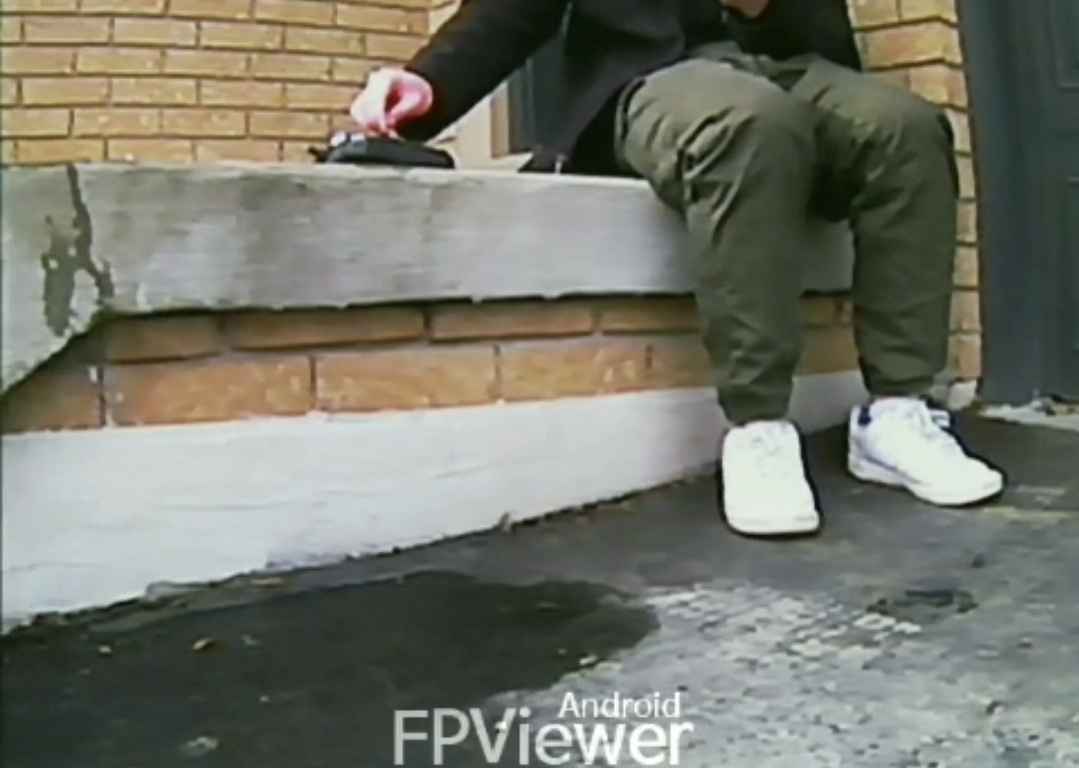
The suspension system was evaluated on different surfaces—gravel, grass, and uneven terrain. Motor speed and torque were adjusted through PWM tuning. The camera system was tested for latency, and steering responsiveness was refined.
Results
The final rover was capable of navigating different terrains, steering dynamically, and streaming live video. Through numerous challenges—3D printing failures, motor driver issues, and debugging control signals—I developed a deeper understanding of multidisciplinary engineering.