Overview
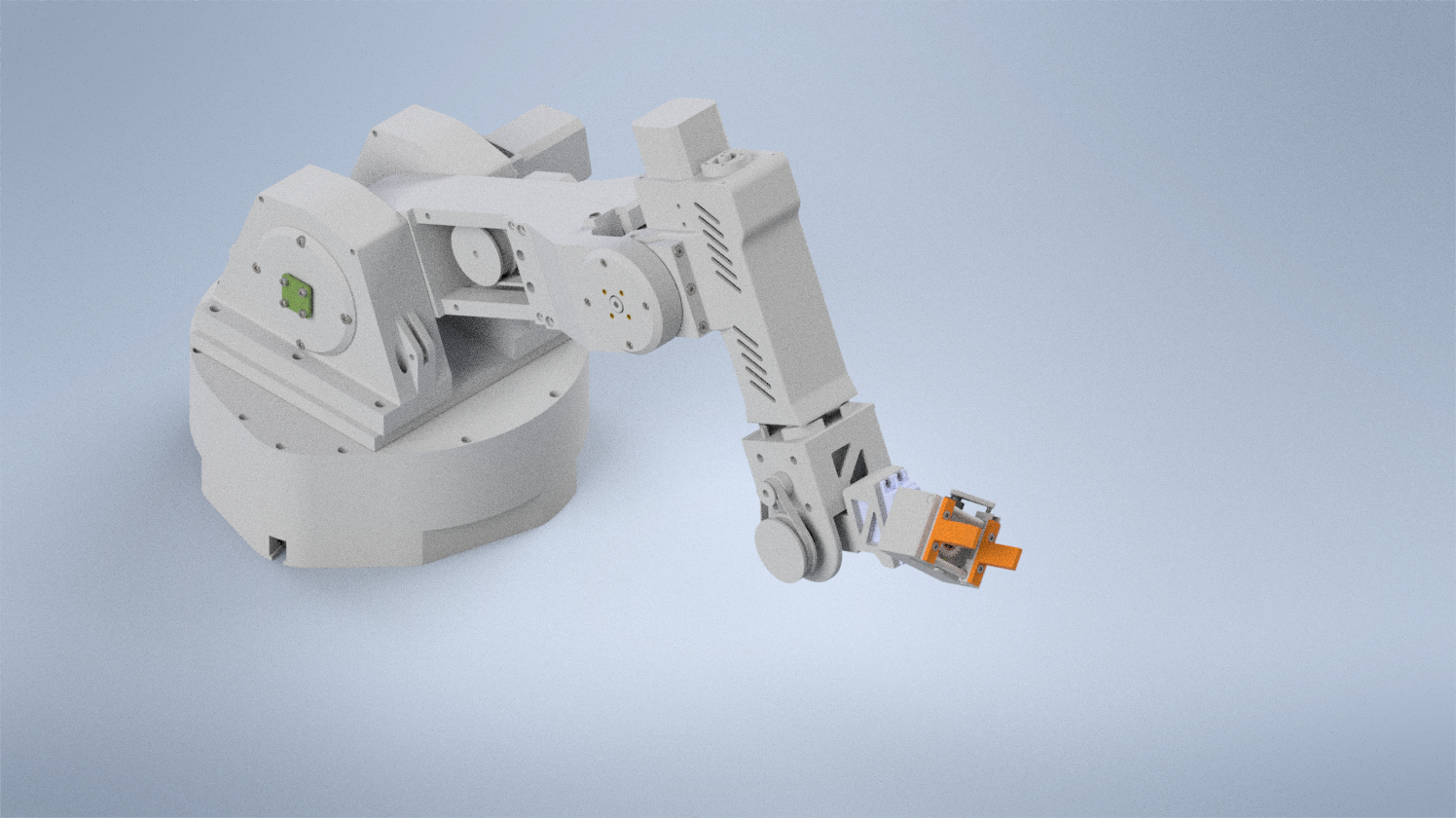
A 6 degree-of-freedom robotic arm built from 27 unique 3D printed parts, driven by cycloidal gear reducers and controlled via gui. The project covers the full stack from mechanical design and manufacturing through inverse kinematics and simulation in Gazebo.
Problem
I wanted to challenge myself to build a 6 degree-of-freedom robotic arm completely from scratch, as a way to explore robotics and understand each aspect of it in the learning process. That meant designing the mechanical structure, building custom gearboxes, wiring the electronics, writing the firmware, and developing the software stack for joint control and motion planning.
Mechanical Design
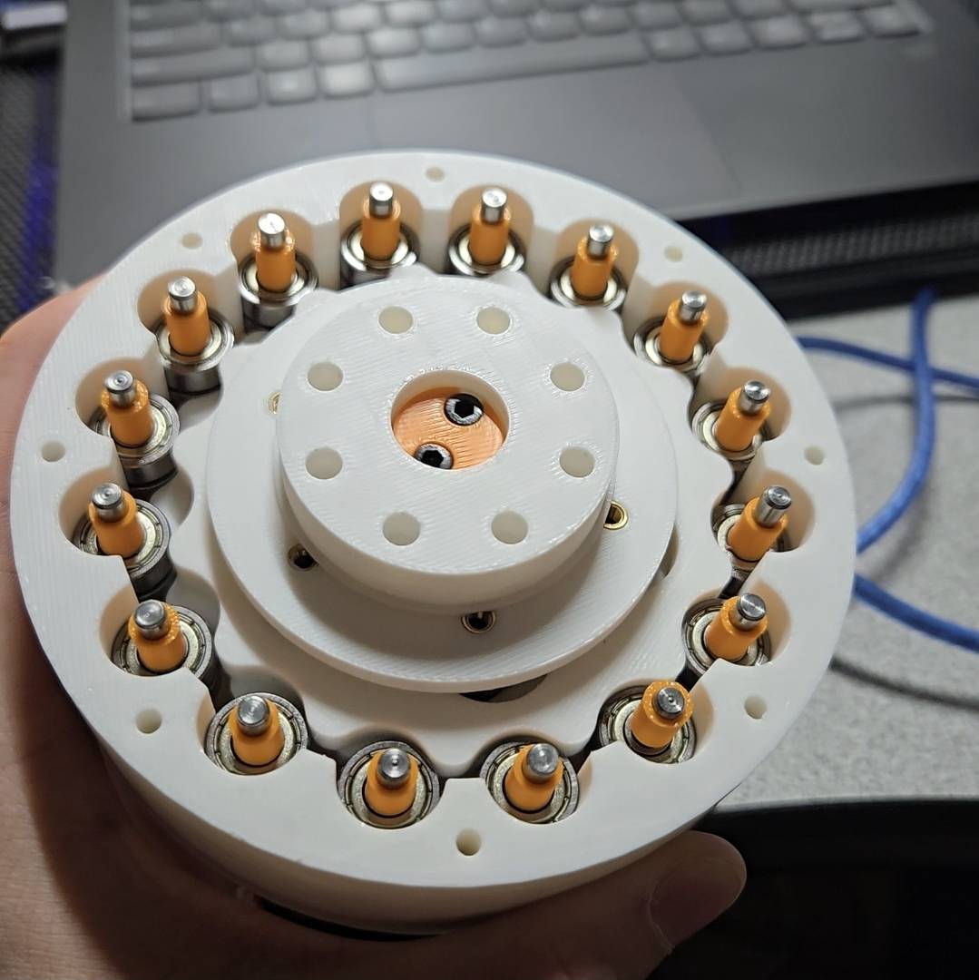
3D Printed Structure
The arm is composed of 27 unique 3D printed components, produced through rapid iterative prototyping cycles. Each part was refined across multiple print iterations to dial in tolerances for bearing press-fits, shaft interfaces, and fastener pockets.
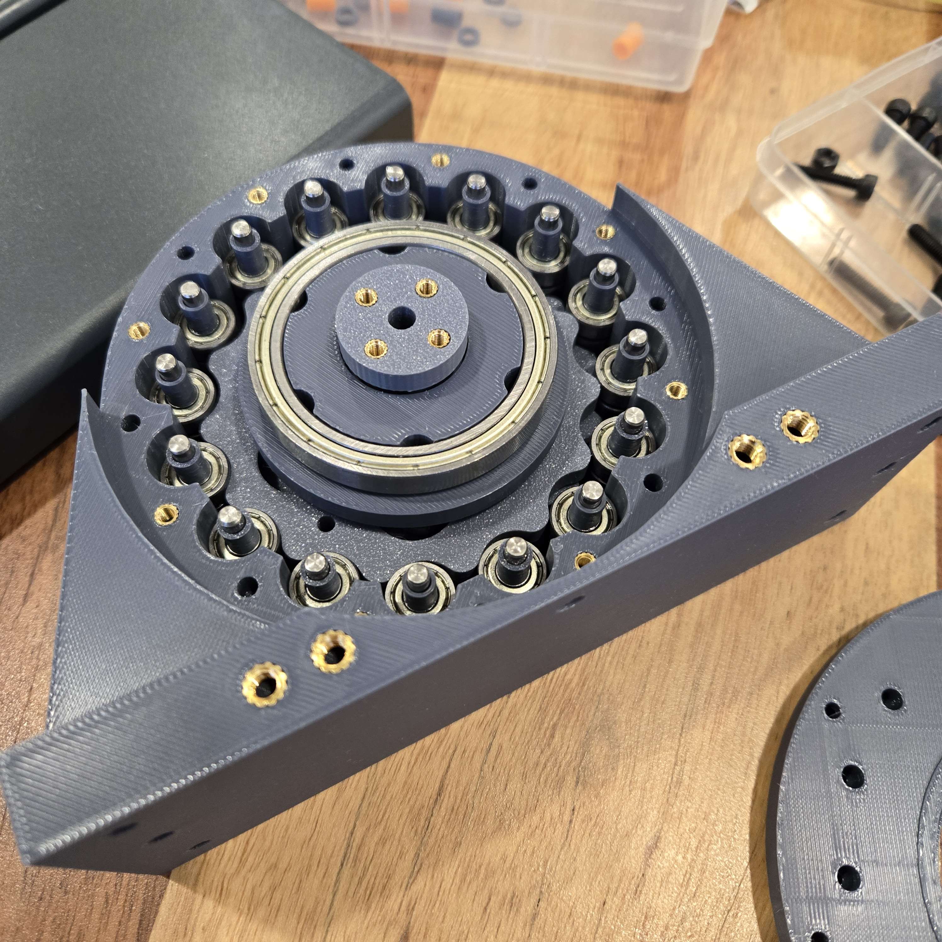
Cycloidal Gear Drives
Each joint uses a custom 15:1 cycloidal gear drive, delivering 12 Nm of torque while maintaining low backlash. Cycloidal reducers were chosen over planetary gearboxes for their compactness and near-zero backlash characteristics, which are critical for repeatable positioning at each joint.
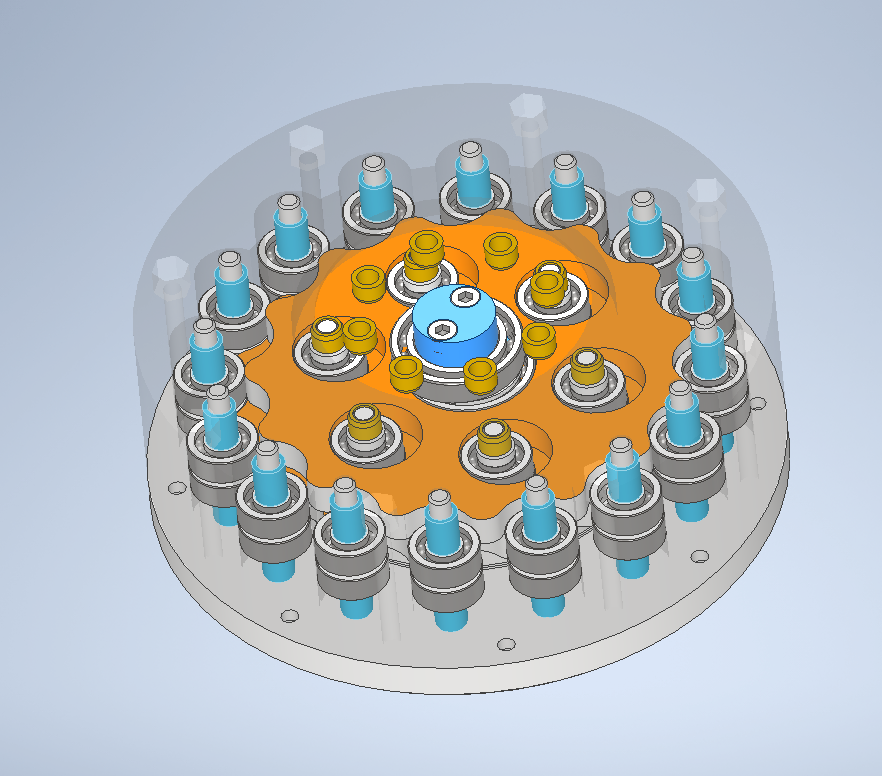
- Problem: I tried a few printed gearbox layouts first, but most were either too bulky, too much backlash, or not suited for a robotic arm joint.
- Constraints: I needed something compact, backdrivable, easy to print, and strong enough to get useful torque, while holding fairly tight tolerances.
- Solution: I settled on a cycloidal gearbox since it fit the robotics application well, and the full stage only used about $10 of material including printed parts, dowels, and bearings.
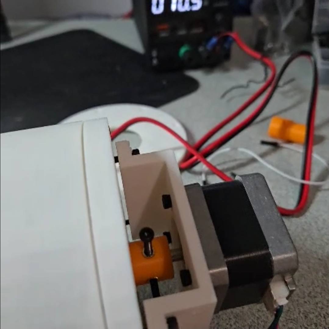
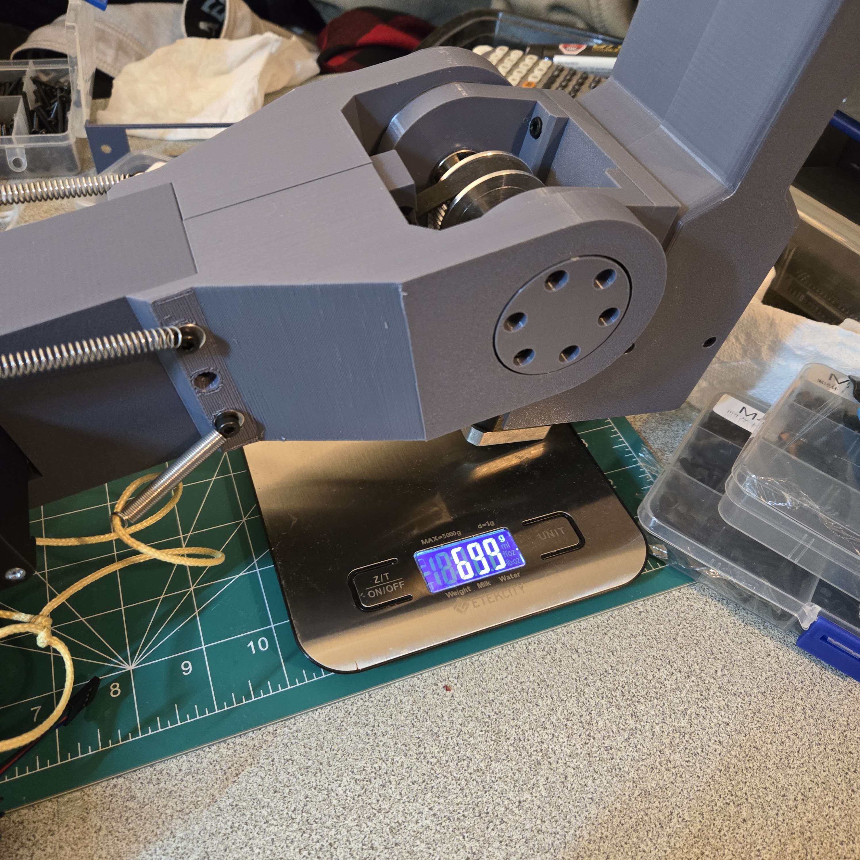
- Results: I tested it with a fake arm and a 2 N·m NEMA 17 by pushing on a scale, then estimated output torque with
T = F × r, where force from the scale times arm length gave the effective joint torque.
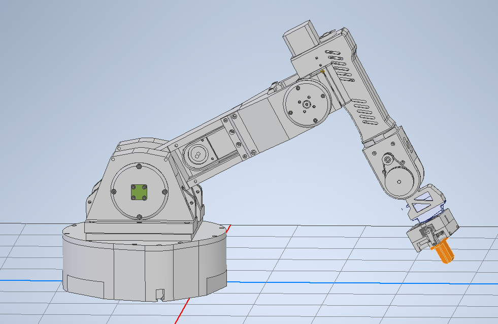
Full Mechanical Build
- Problem: The full arm needed 6 joints that were stiff and smooth, but still light enough that the lower joints were not overloaded.
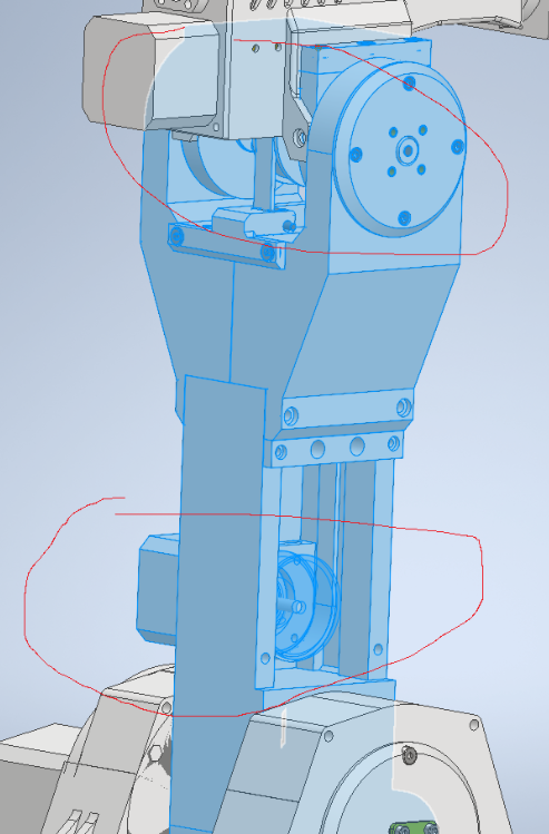
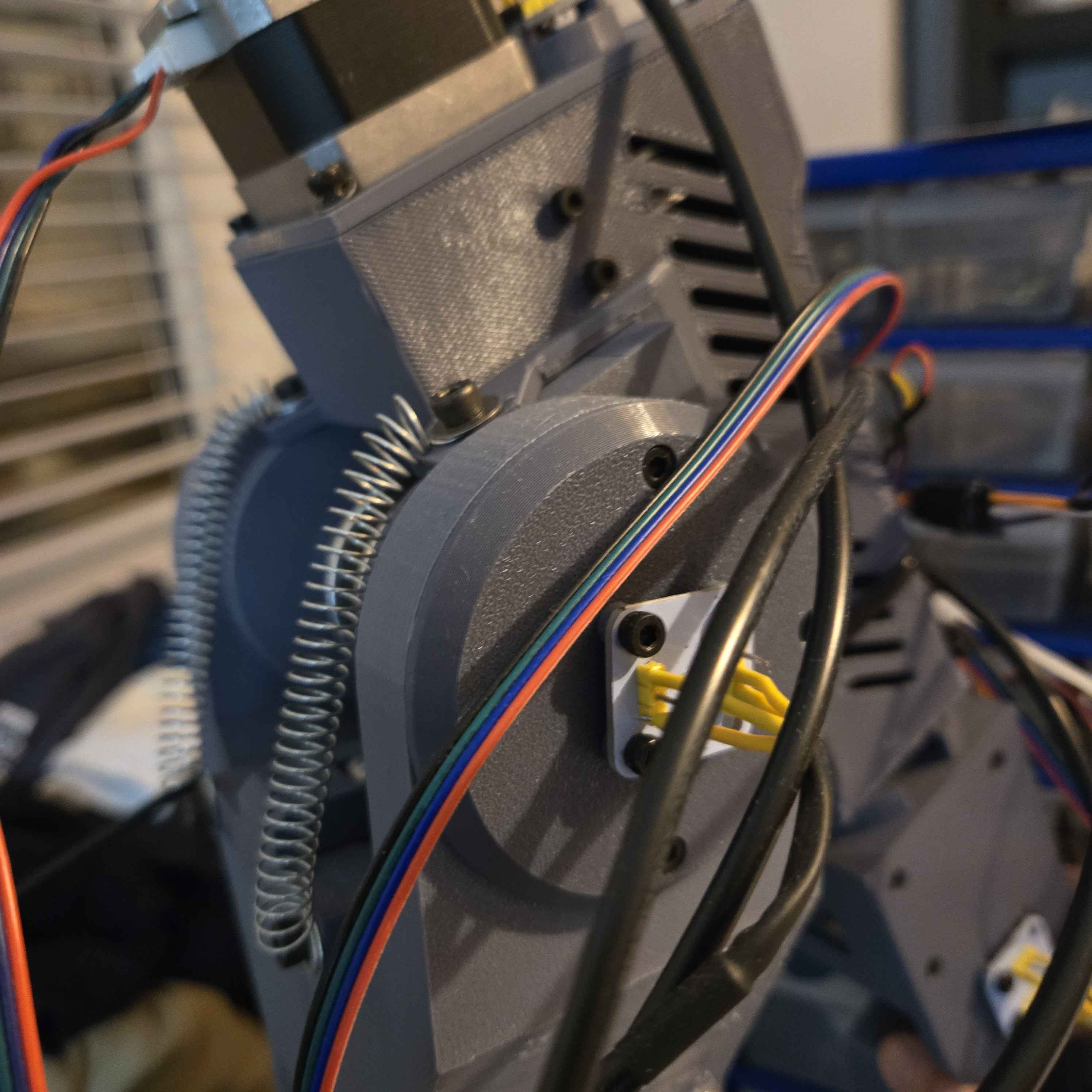
- Constraints: A big constraint was keeping everything light while still designing for manufacture and assembly, so I used carbon fiber rods for strength and alignment, heat set inserts for assembly, bearings for smoother joints, and belt pulleys because they made tensioning simple.
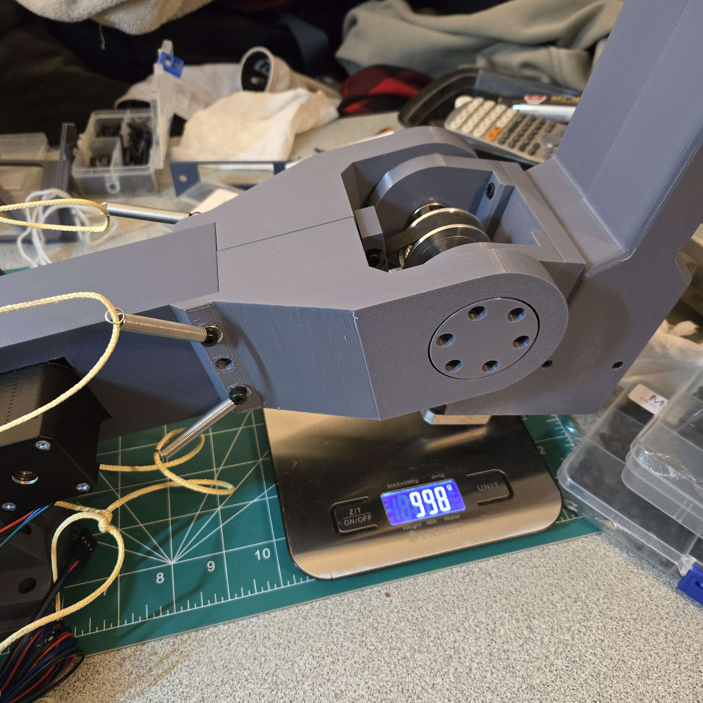
- Solution: The biggest design choice was placing the joint 2 motor at the bottom of the shaft and driving the upper joint with a long belt, which moved more mass closer to the base. Even with that setup the build was still heavier than I wanted, so after some research I added springs to provide a counteracting force and take load off the joints.
- Results: Moving the motor lower reduced the effective torque from the motor and gearbox weight on the lower joints, and in testing the spring counterbalance reduced the effective weight seen by some joints by about 30%.
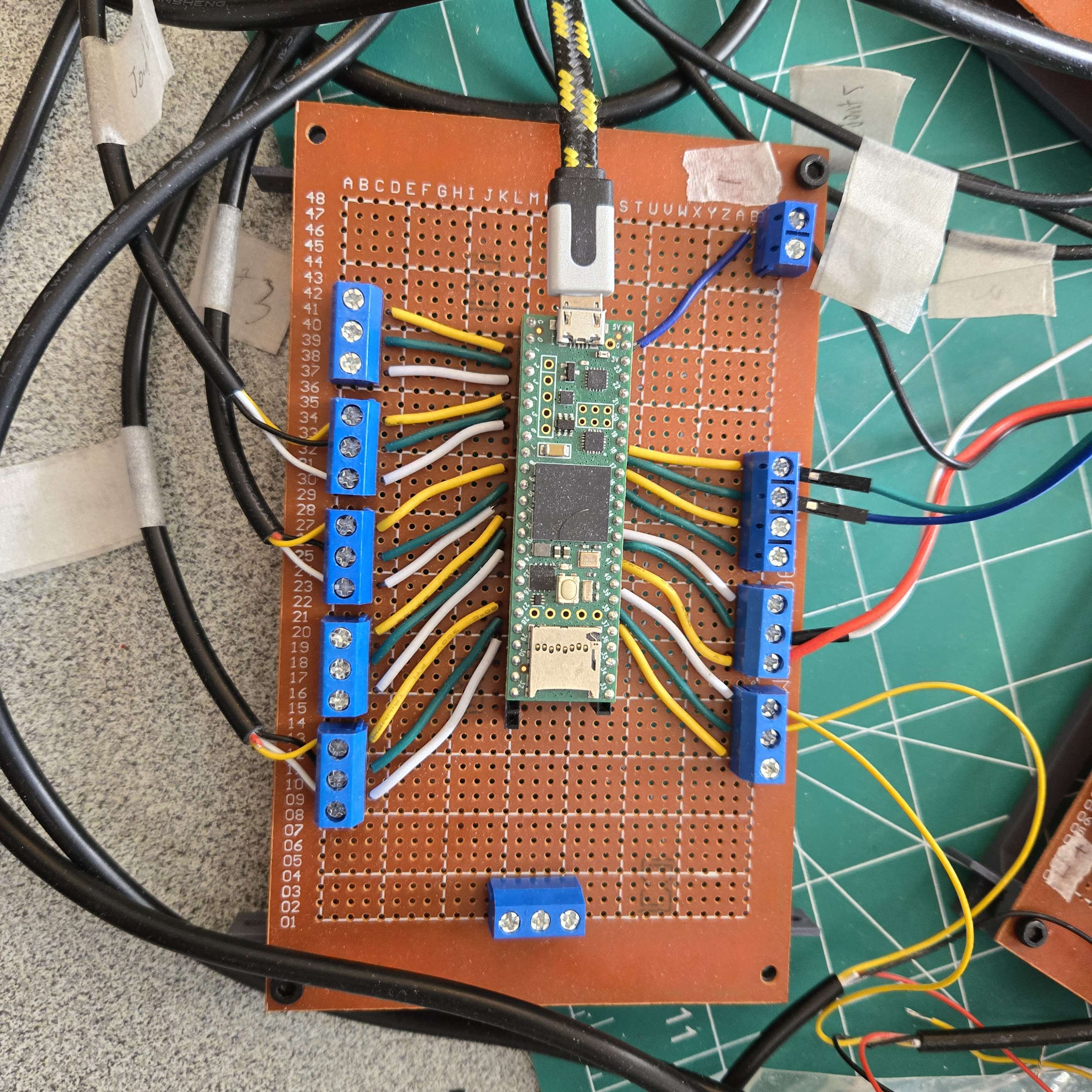
Electronics & Wiring
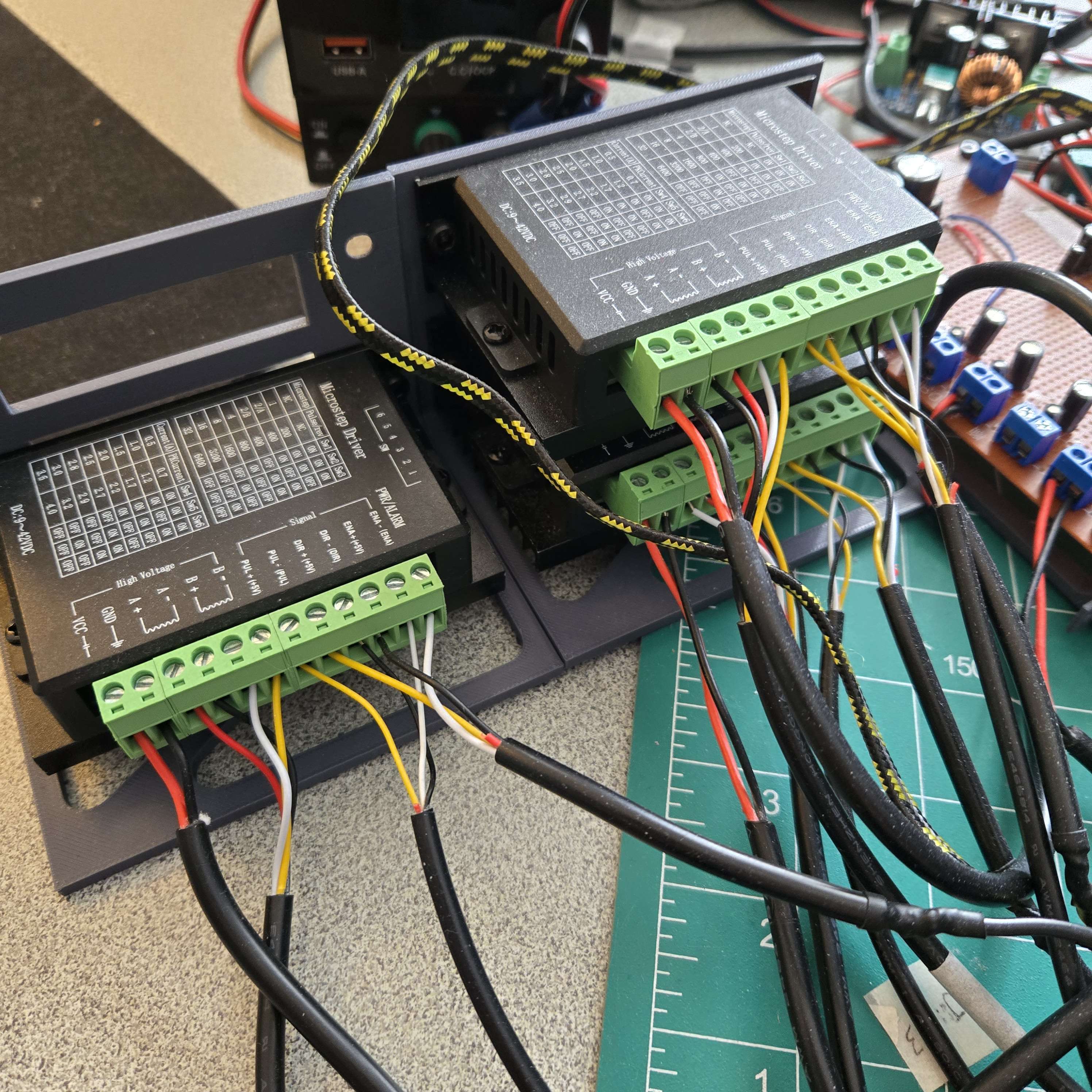
- Electronics summary:
- Teensy 4.1 microcontroller
- 5 TB6600 motor controllers
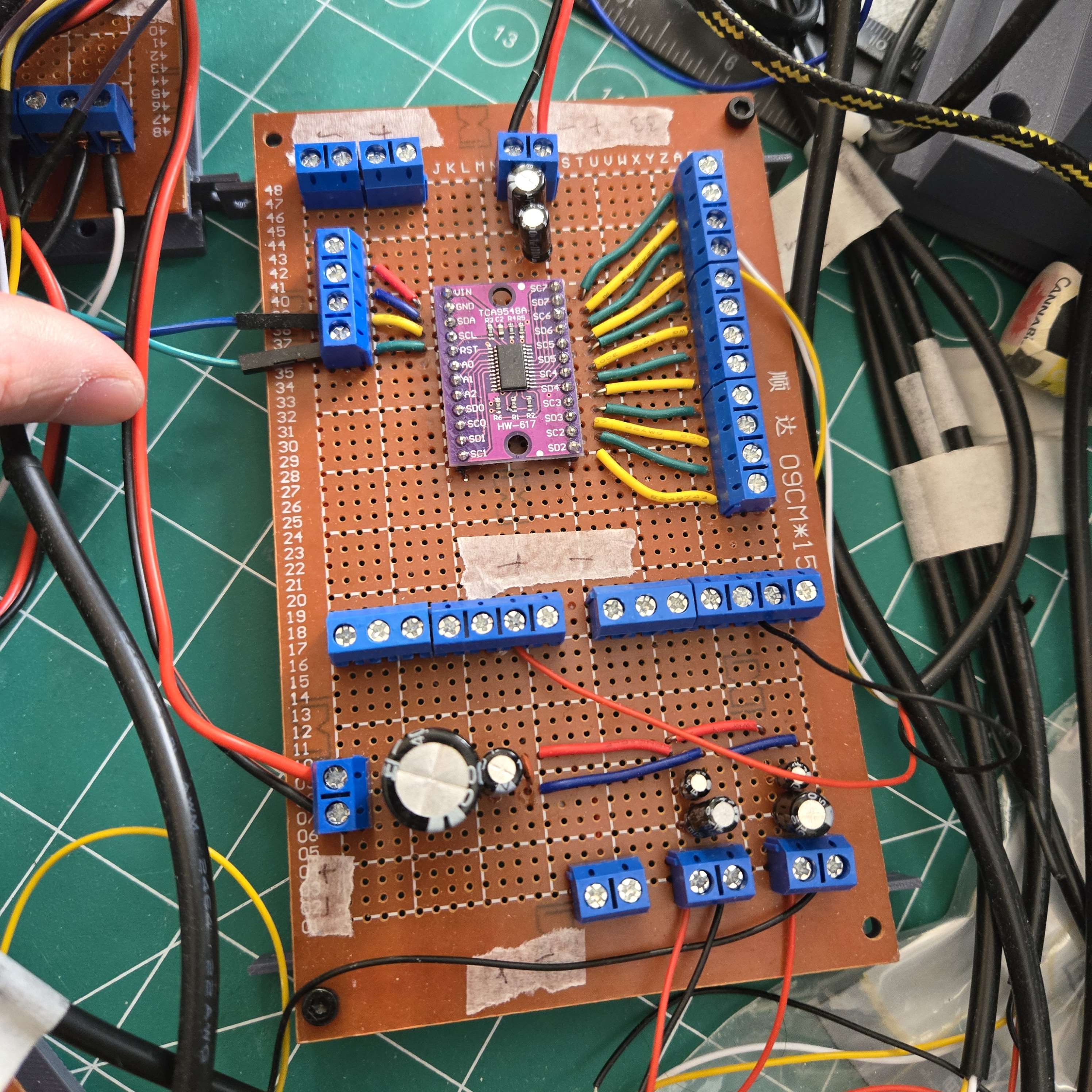
- 1 TCA9548A multiplexer
- 4 AS5600 magnetic encoders
- 1 NEMA 17 at 1.5 A and 0.7 N·m
- 1 NEMA 17 at 2 A and 0.59 N·m
- 1 NEMA 17 at 1 A and 0.29 N·m
- 2 XH-M401 buck converters
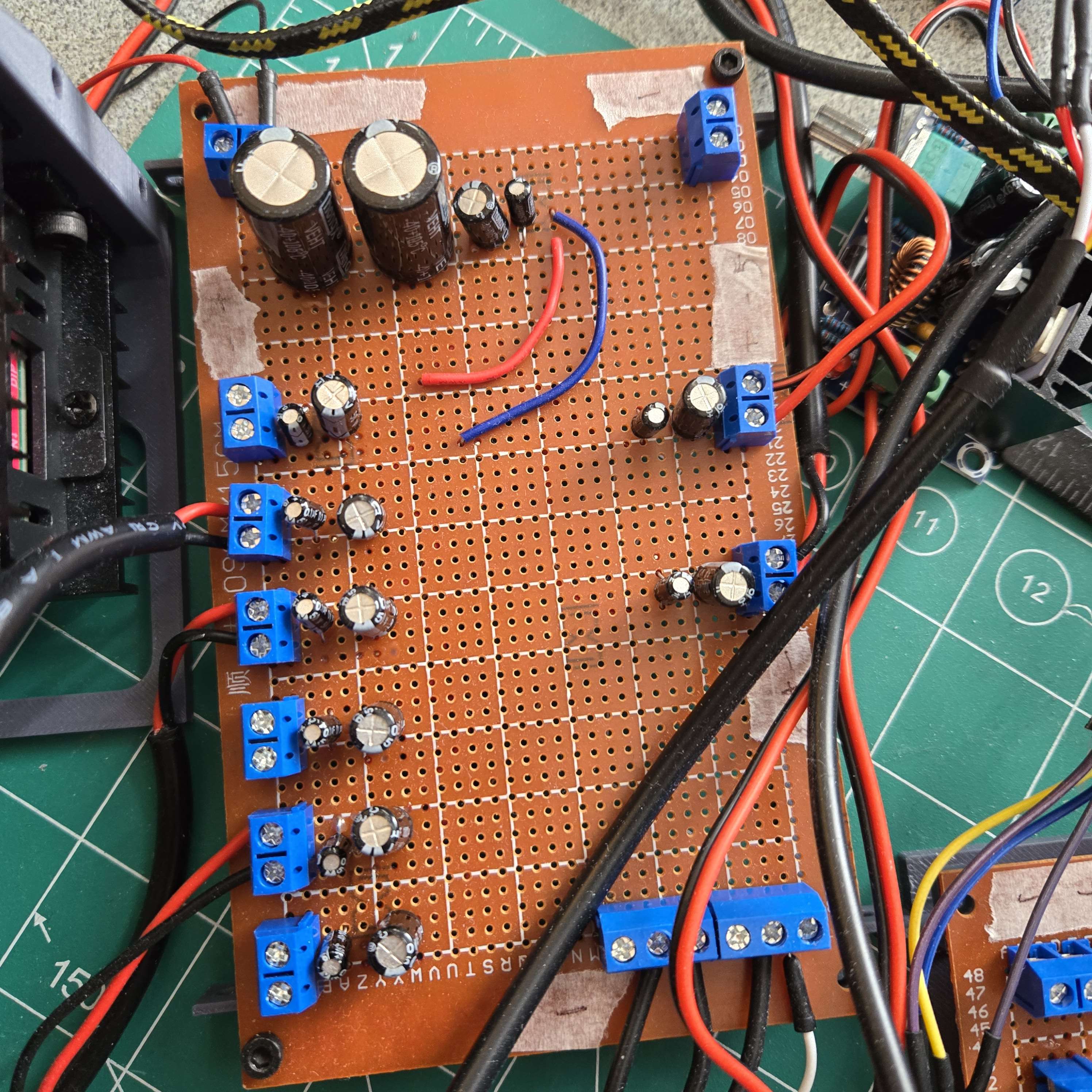
- Power distribution: A 12 V bench supply feeds a distribution hub. From there, 12 V goes directly to each TB6600 driver and also into DC-DC buck converters, where it is stepped down to 5 V and 3.3 V. The 5 V rail powers the 25 kg digital servo on the end effector, while the 3.3 V rail powers the Teensy 4.1, the TCA9548A multiplexer, and the AS5600 magnetic encoders.
- Noise control: I used a range of 0.1, 1, 100, and 1000 uF capacitors across the system. The smaller capacitors help catch higher-frequency noise and fast current spikes, while the larger bulk capacitors help with slower load changes and reduce supply sag.
- Results: This mattered because the digital servo had very choppy current draw and added noise to the supply, which could disturb the AS5600 encoder readings if everything shared the same line too closely. Splitting rails and adding decoupling made the encoder feedback much more stable.
Software & Controls
Python Control UI
-
Purpose: I built a Python GUI to make testing and operating the arm much easier during development.
-
Features: The interface lets me switch modes, set joint angles, run calibration routines, send commands manually, and visualize the serial commands being sent to the Teensy microcontroller.
-
Result: Having one control panel sped up testing a lot and made it easier to debug the full system without constantly changing embedded code.
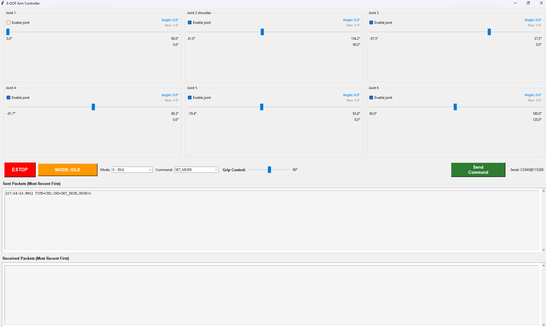
Python based GUI
Serial Communication Protocol
- Problem: The controller needed to send commands reliably while also listening for live joint-angle feedback from the Teensy.
- Solution: I created a custom serial communication protocol that continuously polls the Teensy for joint data while still allowing outbound commands from the GUI.
- Reliability: I added acknowledgements to confirm packets were received, which helped avoid missed commands during testing and calibration.
PID Joint Control
- Architecture: I used a separate PID loop for each joint so all 6 axes could be controlled independently.
- Driver design: The standard Arduino stepper libraries were too choppy for 6 simultaneous joints, so I wrote a custom motor driver using interrupts and timing logic to step all motors smoothly at the same time.
- Control loop: Encoder angle was used to calculate the position error for each joint, and that error was fed into the PID controller, where the output determined motor direction and step speed.
- Results: This made the arm more precise, improved positioning accuracy, and let the joints move more efficiently under load.
Inverse Kinematics
Inverse kinematics algorithms compute the required joint angles from a desired end-effector position and orientation. This allows the arm to be commanded in Cartesian space rather than requiring manual specification of each joint angle.
- I broke the kinematics into 2 parts: an RRR arm and a spherical wrist manipulator.
- For positioning, I isolate the wrist joint and solve the XZ-plane geometry with joint 2 and joint 3, while joint 1 sets the base yaw.
- For orientation, joint 4, joint 5, and joint 6 control the wrist, with joint 4 and joint 6 handling roll and joint 5 handling pitch.
- From a desired end-effector position and orientation, the required joint angles can then be solved directly.
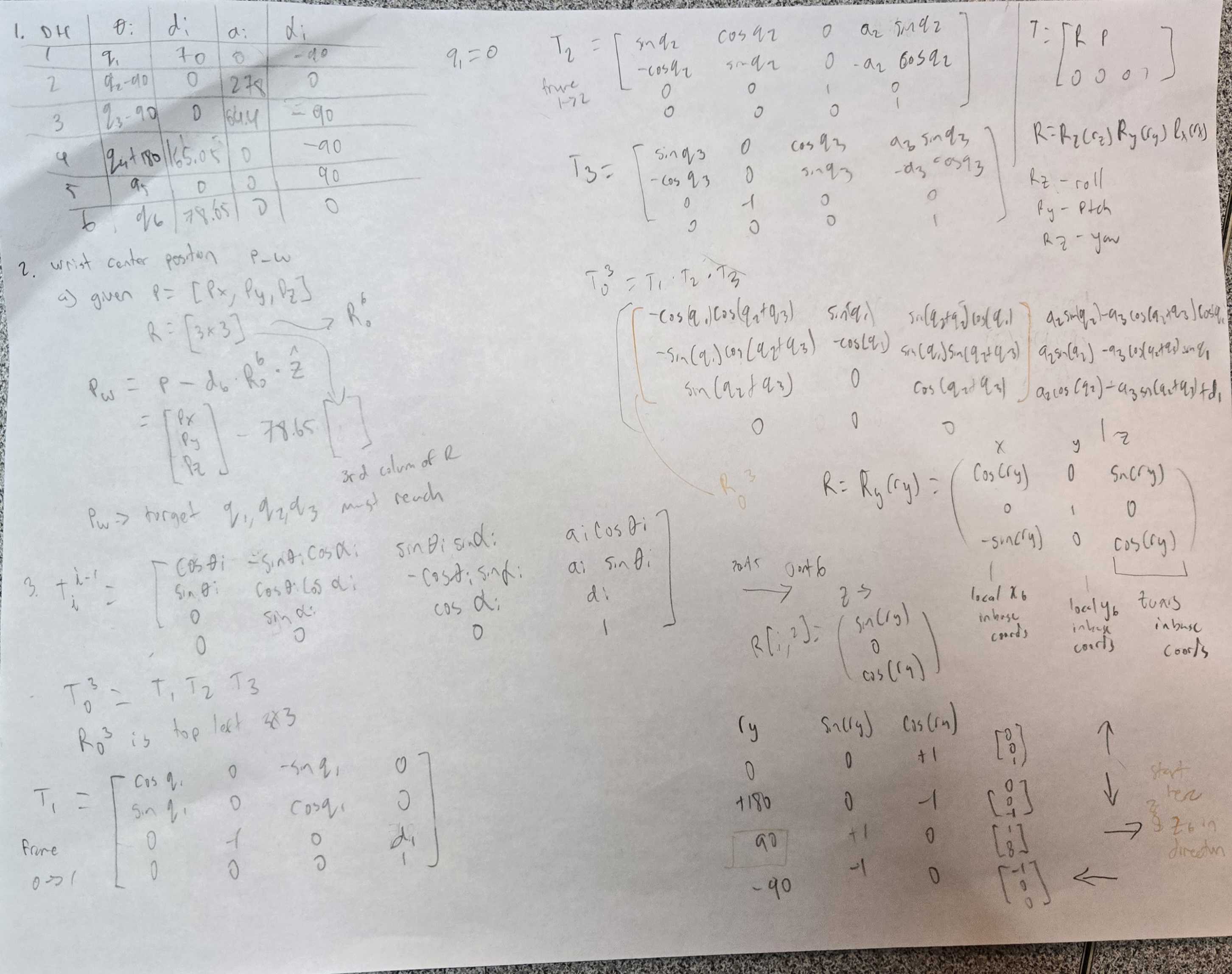
- I used a Denavit-Hartenberg model to define frame assignments and link dimensions for the full arm.
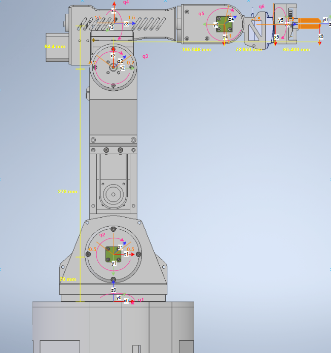
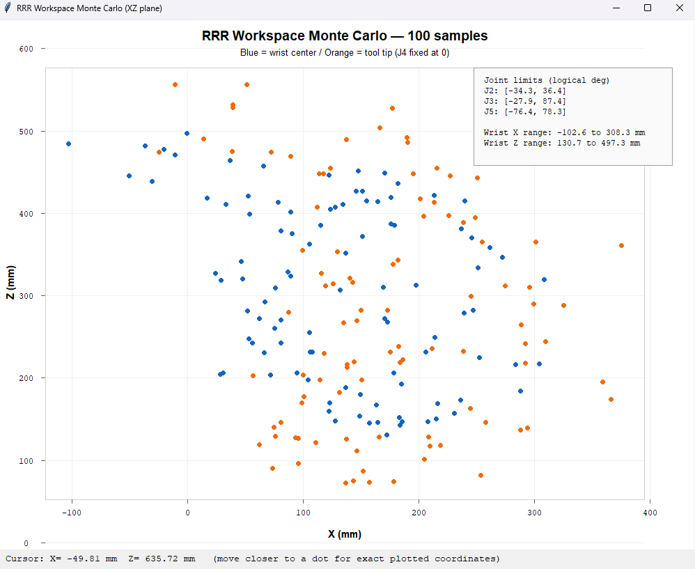
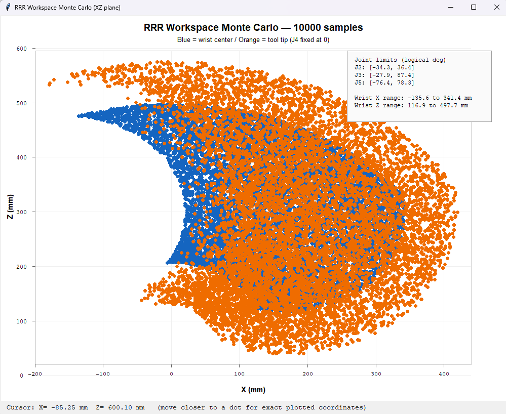
- I estimated the wrist and end-effector workspace in the XZ plane by setting joint 4 = 0 and joint 6 = 0 and plotting constrained random joint values.
- With 100 samples the boundary is rough, while 10000 Monte Carlo samples give a much clearer reference for all reachable positions.
Results
The completed arm achieves smooth, controlled motion across all 6 axes with enough torque and precision for pick-and-place tasks. The ROS2 integration enables future expansion into vision-guided manipulation and more advanced path planning.